Automatic knife replacing device for food cutter

A technology of automatic knife changing and cutting machine, which is applied in the fields of food forming, food science, metal processing, etc., can solve the problem that the cutting machine cannot be applied, and achieve the effect of improving work efficiency and simplifying the operation of knife changing.

Inactive Publication Date: 2015-06-03
北海市京海智能科技有限公司
View PDF5 Cites 14 Cited by
  • Summary
  • Abstract
  • Description
  • Claims
  • Application Information

AI Technical Summary

Problems solved by technology

When cutting diced foods of different sizes, the structure of this cutting machine needs to be stopped and the cutters need to be replaced manually. In order to reduce labor intensity and improve work efficiency, it is necessary to develop a food cutting machine with automatic tool changer

Method used


Image

  • Automatic knife replacing device for food cutter
  • Automatic knife replacing device for food cutter
  • Automatic knife replacing device for food cutter

Examples


Embodiment 1

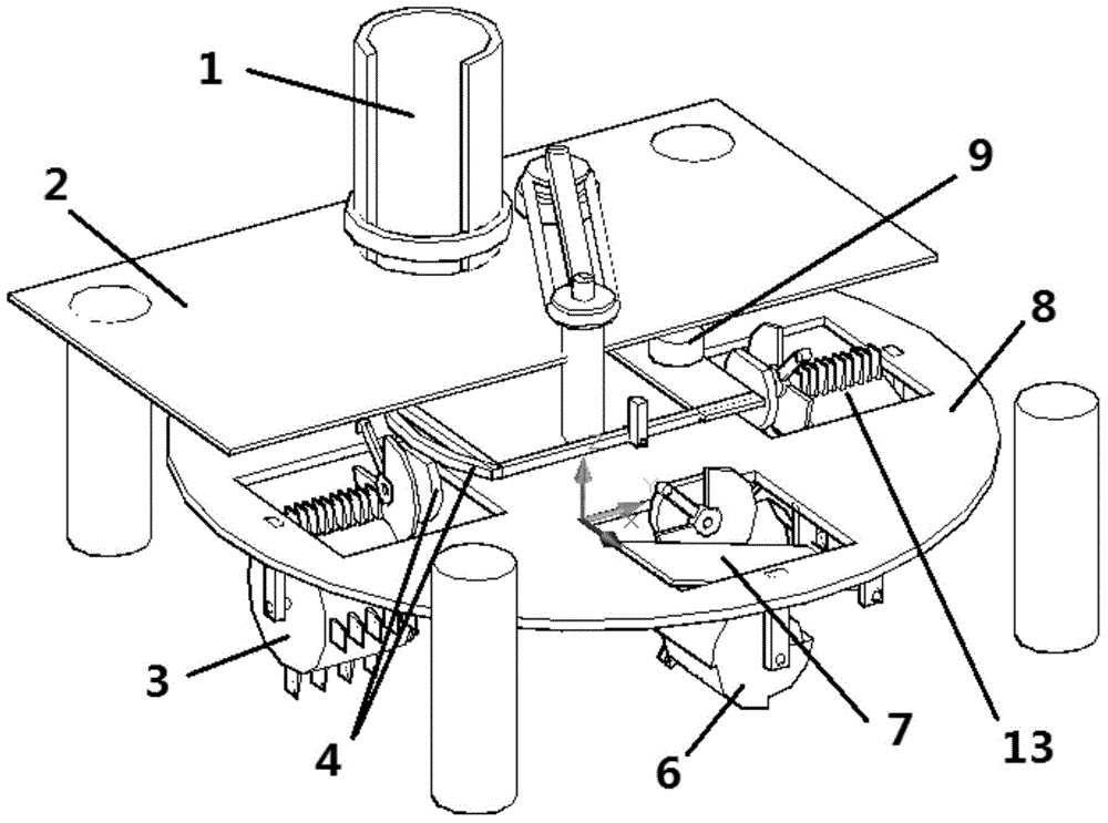
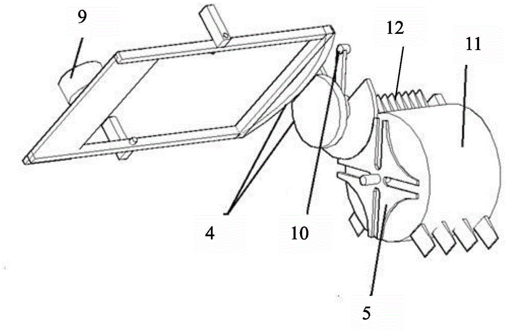
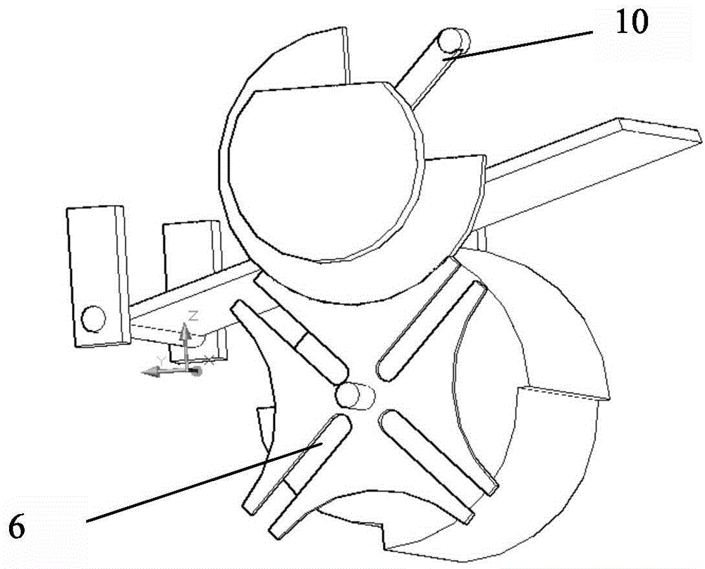
[0031] Both the first tool post 3 and the second tool post 13 are provided with three working stations 12 and an empty station 11, and a plurality of tools with the same interval are arranged on the working station 12 and the interval is different from other working stations. The distance between the cutters on the position 12 is different. The third tool rest 7 is a cutting knife, which is provided with 3 working positions. The height of the cutting knife can be adjusted by adjusting the working positions. The second tool rest 13 and the first tool rest 3 At an angle of 180°, the third tool holder 7 and the first tool holder 3 are at an angle of 270°. The original material is put into the material barrel 1, and the turntable 8 rotates to drive the knives on the first knife holder 3, the second knife holder 13 and the third knife holder 7 to cut the food. According to the different tool selection, the original food material can be Processed into pieces, strips, and D-shaped fin...

Embodiment 2

[0036] Both the first tool post 3 and the second tool post 13 are provided with three work stations 12 and an empty station 11, a total of four stations. The working station 12 is provided with a plurality of tools with the same interval and the interval is different from the tool intervals on other working stations 12. The third tool rest 7 is a cutting tool, which is provided with 4 working stations, By adjusting the working position to adjust the height of the cutting knife, the second tool rest 13 and the first tool rest 3 form an angle of 180°, and the third tool rest 7 and the first tool rest 3 form an angle of 270°. The original material is put into the material cylinder 1, and the turntable 8 rotates, driving the knives on the first, second and third knife holders to cut the food. According to the different selection of knives, the original food materials can be processed into slices and strips. , Ding-shaped finished materials. Finally, it is collected by the portion ...


PUM


Abstract

The invention discloses an automatic knife replacing device for a food cutter. The automatic knife replacing device comprises a first knife rest, a second knife rest, a third knife rest, a drive device and a control device, wherein the second knife rest and the first knife rest form an angle of 180 degrees; the third knife rest and the first knife rest form an angle of 270 degrees; a plurality of working stations and an empty station are arranged on each of the first knife rest and the second knife rest; a plurality of knives with the same intervals are arranged on each working station of the first knife rest and the second knife rest, and the interval is different from the interval of knives on other working stations; the first knife rest, the second knife rest and the third knife rest are driven by a slot wheel mechanism. When the automatic knife replacing device needs to cut vegetables of different sizes, incomplete gears are driven by an electromagnet to be engaged, and the knife rests are driven to rotate through the slot wheel mechanisms, so that the working stations are replaced until the knife rests rotate to the working stations meeting the needs, and the automatic knife replacement is realized. The labor intensity is reduced and the working efficiency is improved.

Description

Technical field [0001] The invention relates to a knife changing device, in particular to an automatic knife changing device of a food cutting machine. Background technique [0002] At present, household and restaurant cutting is generally done by manual or food cutting machine, manual cutting is time-consuming and laborious, especially restaurants need to hire multiple people to do it. Existing cutting machines need to use two sets of perpendicular blades to cut the D-shaped finished material. By squeezing the original material, it passes through the two sets of vertical blades to cut the original material into a square shape. The turntable and the knives on it cut the grid-shaped material into a D-shaped finished material. The structure of this cutting machine needs to be stopped and manually replaced when cutting different sizes of D-shaped food. The existing cutting machine cannot be suitable for users in the catering industry and food processing industry with more urgent ne...

Claims


Application Information

Patent Timeline
Patent Type & Authority Applications(China)
IPC IPC(8): A23P1/02B26D3/18
Inventor 白涵卢两尊廖启征郭磊吴奇
Owner 北海市京海智能科技有限公司
Why Eureka
Try Eureka