Self-positioning disc-type hob device

A self-positioning and hob technology, which is applied in mining equipment, earthwork drilling, tunnels, etc., can solve the problem that the hob cannot be both firm and easy to replace, so as to ensure stability, firm and reliable installation, and shield tunneling The effect of convenient construction

Active Publication Date: 2012-08-15
SHANGHAI TUNNEL ENG CO LTD +1
View PDF5 Cites 5 Cited by
  • Summary
  • Abstract
  • Description
  • Claims
  • Application Information

AI Technical Summary

Problems solved by technology

[0003] The purpose of the present invention is to provide a self-positioning disc-type hob device to solve the problem that the existing hobs cannot have both firmness and easy replacement

Method used


Image

  • Self-positioning disc-type hob device
  • Self-positioning disc-type hob device
  • Self-positioning disc-type hob device

Examples


Embodiment Construction

[0013] The present invention will be described in detail below in conjunction with the accompanying drawings.

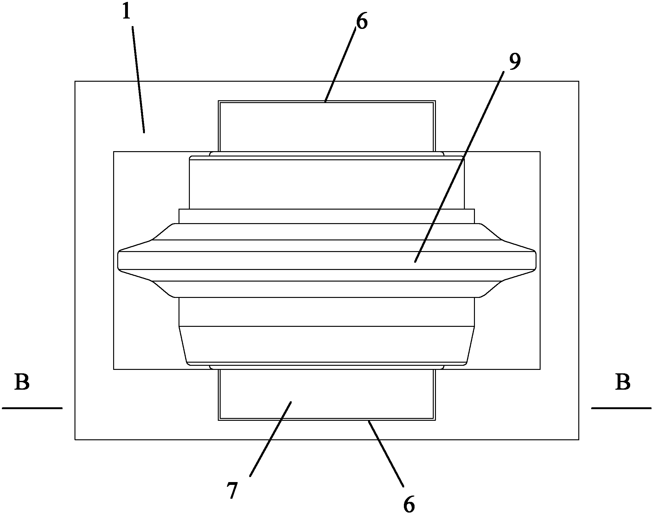
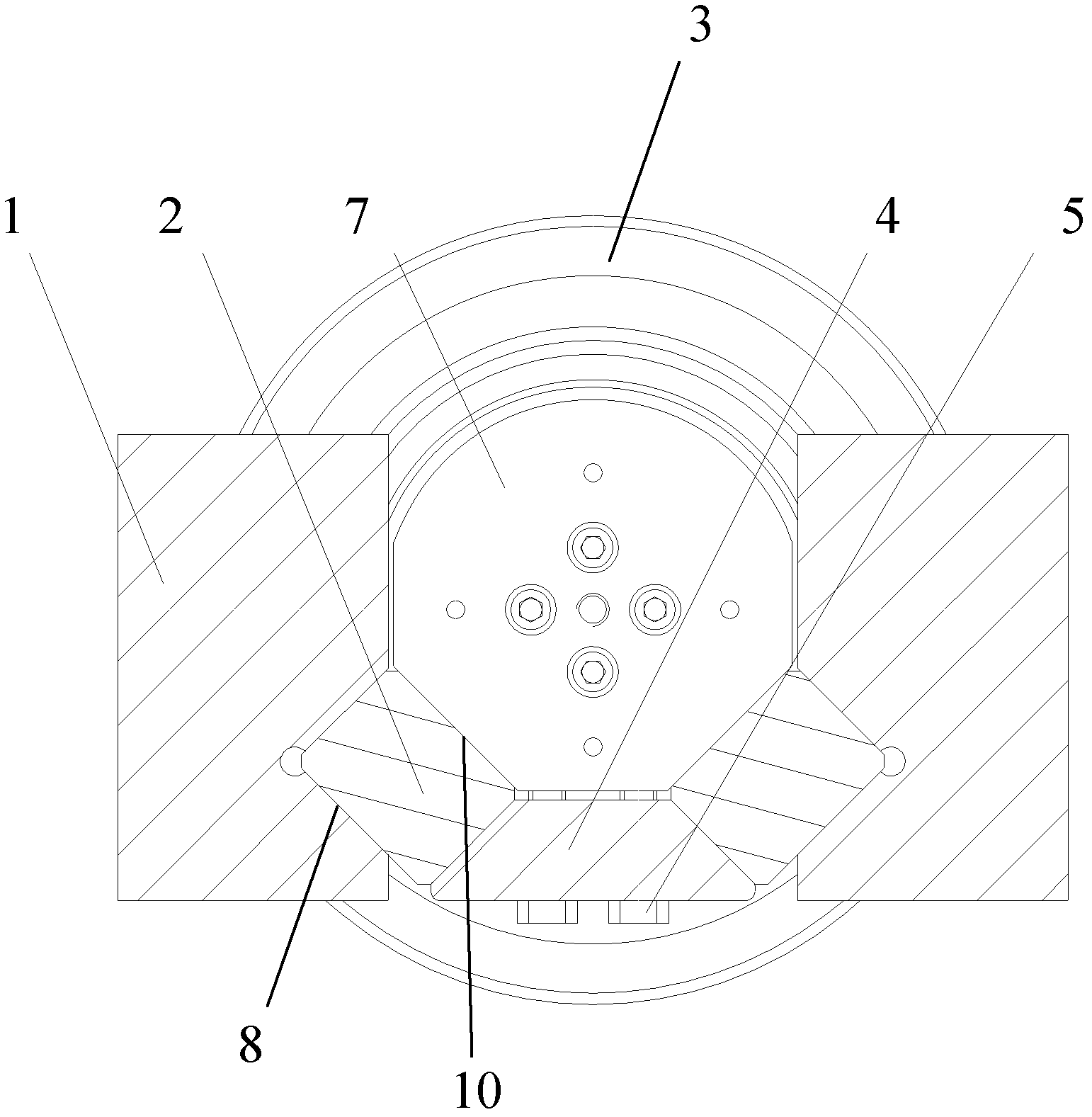
[0014] See figure 1 and figure 2 , which is a schematic diagram of an embodiment of the self-positioning disc hob device of the present invention, figure 2 for figure 1 Sectional view of the B-B' position in the middle. The self-positioning disc-type hob device of the present invention includes a knife box 1 , a hob 3 , a cushion block 2 and a fixed block 4 . Two grooves 6 are respectively arranged on the corresponding two sides of the cutter box 1 for accommodating the cutter shaft 7 of the hob 3 , and two first slopes 8 are arranged in each of the two grooves 6 .

[0015] The hob 3 is arranged in the knife box 1, the hob 3 is a disc-shaped central rotary structure with a blade 9, and a knife shaft 7 is pierced in the middle, and the two ends of the knife shaft 7 are located in the groove 6 of the knife box 1, Four second bevels 10 are arranged on the cutter ...


PUM


Abstract

The invention discloses a self-positioning disc-type hob device, comprising a hob box, a hob, cushion blocks and fixed blocks. Grooves are arranged at two corresponding sides of the hob box respectively, and two first inclined planes are arranged in the two grooves respectively; the hob is installed in the hob box, a hob shaft is arranged at the centre of the hob, four second inclined planes corresponding to the four first inclined planes are arranged on the hob shaft respectively, and spaces exist between the corresponding first inclined planes and second inclined planes (the first inclined planes and the second inclined planes are parallel at equal intervals during assembly); the four cushion blocks are cushioned among the corresponding first inclined planes and the second inclined planes respectively; and the two fixed blocks are next to the four cushion blocks and fixedly connected with the hob. The self-positioning disc-type hob device disclosed by the invention can simplify hob-changing operation, ensure firm and reliable installation of the hob, bear reacting force generated by extrusion on rocks, guarantee stability during working, and bring convenience to shield construction.

Description

technical field [0001] The invention relates to a hob device, in particular to a self-positioning disc type hob device with both firmness and easy replacement. Background technique [0002] At present, various shield machines are commonly used in underground tunnel construction. Whether it is a TBM (Tunnel Boring Machine, Tunnel Boring Machine) for hard rock cutting or a composite shield for rock-soil mixed formations, hobs will be installed. The hob is a central rotary structure with a disc-shaped blade. When working, the rock is squeezed by the blade to crush and break it to achieve the purpose of cutting the rock. Because the cutting mainly depends on the extrusion force, the fixed end of the hob must be firm and reliable, and can resist the reaction force generated by the extrusion rock. At the same time, in the use of the tool, when the blade is worn or damaged, the tool must be changed. Therefore, the assembly structure of the hob must take into account both firmnes...

Claims


Application Information

Patent Timeline
IPC IPC(8): E21D9/08
Inventor 王伟钢刘峰王兴梁赟露
Owner SHANGHAI TUNNEL ENG CO LTD
Why Eureka
Try Eureka