Non-contact power supply device for smart tool holder
A technology of non-contact power supply and power supply device, applied in the direction of circuit devices, battery circuit devices, collectors, etc., can solve the problems of not being able to adapt to high speed, difficult to change tools, low power, etc., to achieve convenient tool change operation and no heat generation , high power effect
- Summary
- Abstract
- Description
- Claims
- Application Information
AI Technical Summary
Problems solved by technology
Method used
Image

Examples
specific Embodiment approach 1
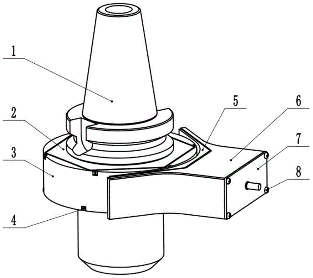
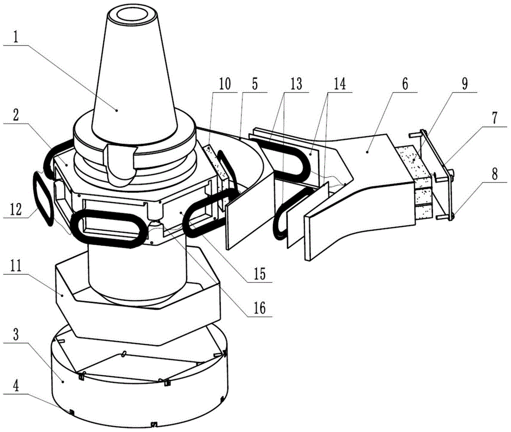
[0046] Specific implementation mode one: combine Figure 1 to Figure 6 Describe this embodiment, the non-contact power supply device for intelligent knife handle described in this embodiment, the receiving end device includes a receiving end circuit 10, a receiving coil group 12 and a receiving bracket 2;
[0047] The receiving bracket 2 is sleeved on the handle 1 and rotates with the handle, the receiving coil group 12 is arranged on the outer surface of the receiving bracket 2, and the receiving end circuit 10 is arranged inside the receiving bracket 2;
[0048] The transmitter device includes a transmitter circuit 9, a transmitter coil group 13 and a transmitter bracket 6;
[0049] One side of the launching support is an arc surface, and the transmitting coil group 13 is fixed on the inside of the arc surface of the launching support 6, and the transmitting end circuit 9 is arranged in the inside of the launching support 6;
[0050] The transmitting coil group 13 and the r...
specific Embodiment approach 2
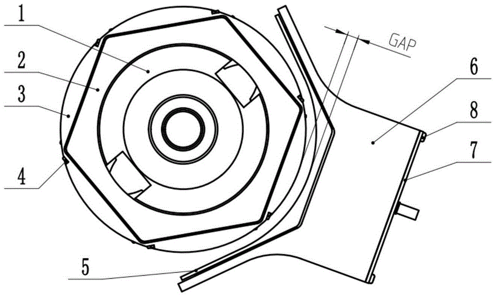
[0054] Specific implementation mode two: combination Figure 7 This embodiment is described. This embodiment is a further limitation of the non-contact power supply device for intelligent knife holder described in the first embodiment. The transmitting coil group 13 includes a coil LC1 and a coil LC2, and the coil LC1 and the coil LC2 are perpendicular to each other. It is arranged on the inner side of an arc-shaped surface of the launch bracket 6;
[0055] The receiving coil group 12 includes a coil RC1 , a coil RC2 , a coil RC3 , a coil RC4 , a coil RC5 and a coil RC6 , and these 6 coils are evenly distributed on the outer surface of the receiving bracket 2 in a regular hexagonal circumferential direction.
[0056] Such as Figure 7 As shown, the layout of the receiving coil group 12 in this embodiment can realize that every time the receiving coil group 12 rotates 30° around the center, one transmitting coil is parallel to one receiving coil, and the effect achieved in thi...
specific Embodiment approach 3
[0057] Specific implementation mode three: combination Figure 8 Describe this embodiment, this embodiment is a further limitation of the non-contact power supply device for intelligent handle described in the second specific embodiment, the transmitting end circuit 9 includes a square wave generating circuit, a MOS tube driving circuit and two DC- AC circuit;
[0058] The DC signal of the power supply is input to the square wave generating circuit, the square wave signal output by the square wave generating circuit is input to the MOS tube drive circuit, and the amplified signal output by the MOS tube drive circuit is input to two DC-AC circuits at the same time, and the two DC -AC circuit respectively output sinusoidal alternating current signal input to coil LC1 and coil LC2;
[0059] The receiver circuit 10 includes an AC-DC circuit, a 3vDC-DC circuit, a 5vDC-DC circuit and a 12vDC-DC circuit;
[0060] The sinusoidal alternating current signal received by the receiving c...
PUM
 Abstract
Description
Claims
Application Information
 - R&D
- Intellectual Property
- Life Sciences
- Materials
- Tech Scout
- Unparalleled Data Quality
- Higher Quality Content
- 60% Fewer Hallucinations
Browse by: Latest US Patents, China's latest patents, Technical Efficacy Thesaurus, Application Domain, Technology Topic, Popular Technical Reports.
© 2025 PatSnap. All rights reserved.Legal|Privacy policy|Modern Slavery Act Transparency Statement|Sitemap|About US| Contact US: help@patsnap.com