A semi-automatic shoe material delivery equipment

A semi-automatic, shoe material technology, applied in footwear, shoe-making machinery, apparel, etc., can solve the problems of lightening and unfavorable labor intensity of feeding personnel

Inactive Publication Date: 2017-09-15
SUZHOU JINGRO TECH
View PDF1 Cites 1 Cited by
  • Summary
  • Abstract
  • Description
  • Claims
  • Application Information

AI Technical Summary

Problems solved by technology

[0005] The technical problem solved by the present invention: the feeding device of a shoemaking machine disclosed in the invention with the application number of 201310147198.1, since the cylinder drives each feed bin to reciprocate in a straight line, therefore, the feeding personnel need to go back and forth on both sides of the feeding mechanism Refilling the vacant silo is not conducive to reducing the labor intensity of the refilling personnel

Method used


Image

  • A semi-automatic shoe material delivery equipment
  • A semi-automatic shoe material delivery equipment
  • A semi-automatic shoe material delivery equipment

Examples


Embodiment Construction

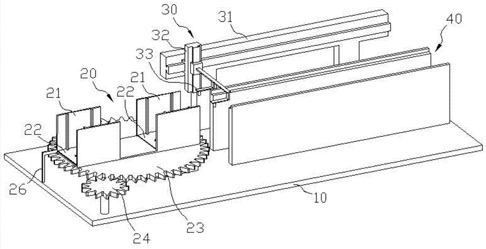
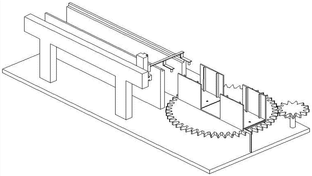
[0025] Such as figure 1 , a semi-automatic shoe material delivery equipment, including a base 10, a material stacking mechanism 20, a material taking mechanism 30, and a conveying mechanism 40, and the material stacking mechanism 20, the material taking mechanism 30, and the conveying mechanism 40 are all installed on the base 10 , the retrieving mechanism 30 is located on the side of the conveying mechanism 40, and the stacking mechanism 20 is located near the starting point of the conveying mechanism 40. start end.

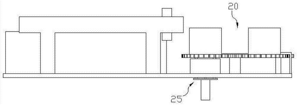
[0026] Such as figure 1 , the stacking mechanism 20 includes two bins 21 symmetrically arranged left and right, and a liftable tray 22 is arranged in the bins 21 . Two feed bins 21 are horizontally installed on the gear disc 23 arranged horizontally. The edges of the whole gear disc 23 are provided with teeth. The center lines coincide, and the symmetrical planes of the two feed bins 21 pass through the center line of the gear plate 23; combine image 3 , ...


PUM


Abstract

The invention discloses a semi-automatic conveying equipment for shoe materials, which includes a material stacking mechanism, a material taking mechanism and a conveying mechanism; the material stacking mechanism includes two material bins arranged symmetrically on the left and right, and a liftable tray is arranged in the material bins; The first silo is installed on the gear plate, and the side of the gear plate is provided with a driving gear meshed with the gear plate; the stacking mechanism also includes a lifting device for lifting the tray in the silo. The replenishing personnel are located at the replenishing station. When the shoe material in one silo is taken out, the refilling personnel drive the gear plate to rotate 180 degrees, and rotate the other silo to the vicinity of the starting point of the conveying mechanism. After that, Refilling personnel refill empty silos. Through the above-mentioned technical scheme, the replenishing personnel only need to drive the gear plate at the replenishing station to replenish the vacant silo, and at the same time, send another full-loaded silo to the starting point of the conveying mechanism In this way, it is conducive to the improvement of work efficiency and the reduction of labor intensity.

Description

Technical field: [0001] The invention relates to the technical field of shoemaking, and in particular relates to a feeding device for inner parts of sports shoes. Background technique: [0002] In the field of shoemaking technology, the production of certain types of shoes requires sewing. For example, the combination of the tongue of the sports shoe, the inner heel of the heel and the main body of the sports shoe requires sewing. According to the traditional processing method, the above-mentioned shoe tongue and the inside of the heel are manually taken by workers, and the workers sew on the sewing machine. For batch production, the production method of manual material removal is not conducive to the improvement of processing efficiency, and the labor intensity of workers cannot be alleviated. [0003] The invention with application number 201310147198.1 discloses a feeding device for a shoemaking machine, which has at least two stacking mechanisms for storing materials. ...

Claims


Application Information

Patent Timeline
Patent Type & Authority Patents(China)
IPC IPC(8): A43D117/00
Inventor 黄超
Owner SUZHOU JINGRO TECH
Why Eureka
Try Eureka