Intracavitary ligating clip for endoscopic surgery

A ligation clip and surgery technology, which is applied in the field of medical devices, can solve the problems of difficulty in matching the card head and card slot, low work efficiency, and fatigue of elastic parts, etc., and achieve the effects of improving the scope of application, low processing cost, and high production efficiency

Inactive Publication Date: 2015-06-03
建德市康华医疗器材有限公司
View PDF6 Cites 4 Cited by
  • Summary
  • Abstract
  • Description
  • Claims
  • Application Information

AI Technical Summary

Problems solved by technology

[0002] In the existing application number 201420055525.0, the hemostatic clip can only provide the function of hemostasis and completely close the lumen. When the secretion inside the lumen cannot be removed in time, it will cause postoperative infection; In the closed state, the elastic parts connecting the upper and lower splints will be fatigued, difficult to remove, and will easily cau

Method used


Image

  • Intracavitary ligating clip for endoscopic surgery
  • Intracavitary ligating clip for endoscopic surgery
  • Intracavitary ligating clip for endoscopic surgery

Examples


Embodiment 1

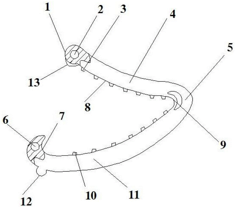
[0029] Such as figure 1 , 3 As shown, the present invention includes an upper splint 4, a lower splint 11, an elastic curved wall 5, an upper anti-skid tooth 3, a lower anti-skid tooth 10, a chuck 1, and a slot 7, and the upper splint 4 and the lower splint 11 are arc-shaped , and cooperate with each other, the upper anti-skid teeth 3 and the lower anti-skid teeth 10 are respectively arranged on the corresponding surfaces of the upper splint 4 and the lower splint 11, and the upper splint 4 and the lower splint 11 Through the fixed connection of the elastic curved wall 5, the free end of the upper splint 4 is provided with the clamp head 1, and the surface of the clamp head 1 opposite to the clamp groove 7 is fixedly provided with a sharp edge 13. The plane 3 where the sharp edge 13 is located is parallel to the plane where the upper splint 4 and the lower splint 11 are located, the free end of the lower splint 11 is provided with the clamping groove 7, and the fixing column ...

Embodiment 2

[0031] Such as figure 1 , 2 , 3, the present invention includes an upper splint 4, a lower splint 11, an elastic curved wall 5, an upper anti-skid tooth 3, a lower anti-skid tooth 10, a chuck 1, and a slot 7, and the upper splint 4 and the lower splint 11 are both arc-shaped, and cooperate with each other, the upper anti-skid teeth 3 and the lower anti-skid teeth 10 are respectively arranged on the corresponding surfaces of the upper splint 4 and the lower splint 11, the upper anti-skid teeth 3, the lower The contact surface of the anti-slip teeth 10 is provided with rough particle grinding lines, which prevent slipping due to the smooth surface of the tissue and bring inconvenience to the operation. The upper splint 4 and the lower splint 11 pass through the elastic curved wall 5 is fixedly connected, the free end of the upper splint 4 is provided with the chuck 1, and the surface of the chuck 1 opposite to the slot 7 is fixed with a sharp edge 13, and the sharp edge 13 is l...

Embodiment 3

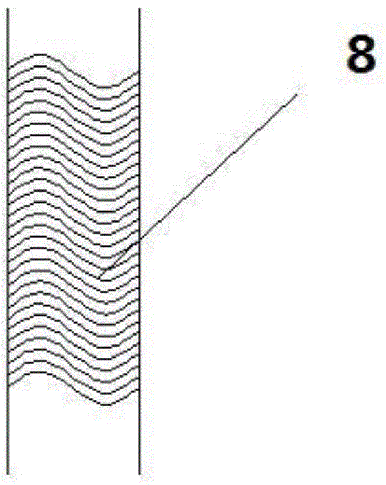
[0033] Such as figure 1 , 3, 4, the present invention includes an upper splint 4, a lower splint 11, an elastic curved wall 5, an upper anti-skid tooth 3, a lower anti-skid tooth 10, a chuck 1, a slot 7, and the upper splint 4 and the lower splint 11 are The upper anti-skid teeth 3 and the lower anti-skid teeth 10 are arranged on the corresponding surfaces of the upper splint 4 and the lower splint 11 respectively, and the upper anti-skid teeth 3 and the The mutual contact surfaces between the lower anti-slip teeth 10 are slopes, such slopes increase the contact area and enhance the hemostatic effect. The upper splint 4 and the lower splint 11 are fixedly connected by the elastic curved wall 5, so The free end of the upper splint 4 is provided with the chuck 1, and the surface of the chuck 1 opposite to the slot 7 is fixed with a sharp edge 13, and the plane 3 where the sharp edge 13 is located is in contact with the upper splint. 4. The plane where the lower splint 11 is lo...


PUM


Abstract

The invention provides an intracavitary ligating clip for endoscopic surgery, which comprises a steel ball, a magnet, a restoring part and reserved perfusion grooves; the number of upper anti-slippage teeth is equal to the number of lower anti-slippage teeth; when the ligating clip is closed, each upper anti-slippage tooth corresponds to one lower anti-slippage tooth, and moreover, the upper anti-slippage teeth are in tight contact with the lower anti-slippage teeth, so that a group of closed upper anti-slippage teeth and lower anti-slippage teeth are formed; the gap between each two groups of upper anti-slippage teeth and lower anti-slippage teeth is the reserved perfusion groove; both ends of the restoring part are respectively fixedly connected with the upper anti-slippage teeth and the lower anti-slippage teeth; the steel ball is embedded in a clip head. The intracavitary ligating clip has the following advantages: after the intracavitary ligating clip is closed, the reserved perfusion grooves can keep microcirculation in tissues, so that necrosis is prevented; the wavy frictional lines on the bottoms of the reserved perfusion grooves and the frictional particles on the surfaces of the anti-slippage teeth can prevent slippage which can cause the intracavitary ligating clip to come off. The arrangement of the restoring part can prevent an elastic curved wall from losing elasticity due to a long time of closing.

Description

technical field [0001] The invention relates to the field of medical instruments, in particular to a ligation clip in an endoscopic operation cavity. Background technique [0002] In the existing application number 201420055525.0, the hemostatic clip can only provide the function of hemostasis and completely close the lumen. When the secretion inside the lumen cannot be removed in time, it will cause postoperative infection; In the closed state, the elastic parts connecting the upper and lower splints will be fatigued, difficult to remove, and will easily cause pain to the patient; at the same time, when the hemostatic clip is used for hemostasis in some tissues with strong toughness, the overall structure will be soft, which will cause difficulty in clamping the head and the slot. Cooperate with the situation. To sum up, the existing hemostatic clips have the technical problems of time-consuming and labor-intensive adjustment and low work efficiency. Contents of the inve...

Claims


Application Information

Patent Timeline
IPC IPC(8): A61B17/122
CPCA61B17/12013A61B17/122A61B2017/12004
Inventor 胡泽张文兴
Owner 建德市康华医疗器材有限公司
Why Eureka
Try Eureka