
Intervertebral implant

An implant and intervertebral technology, applied in the field of intervertebral implants, can solve the problems of high technical price and low stability, and achieve the effect of wide stress range, high stability and improved fusion

Active Publication Date: 2015-06-03
METAL INDS RES & DEV CENT
View PDF8 Cites 2 Cited by
  • Summary
  • Abstract
  • Description
  • Claims
  • Application Information

AI Technical Summary

Problems solved by technology

The overall comprehensive structure implant has the function of fusing the upper and lower vertebral bodies. This technology is relatively expensive, because the upper and lower layers have a single-pore fine-porosity porous structure and low stability.

Method used


Image

  • Intervertebral implant
  • Intervertebral implant
  • Intervertebral implant

Examples


Embodiment Construction

[0050] In order to have a further understanding of the purpose of the present invention, structural features and functions thereof, the relevant embodiments and accompanying drawings are described in detail as follows:

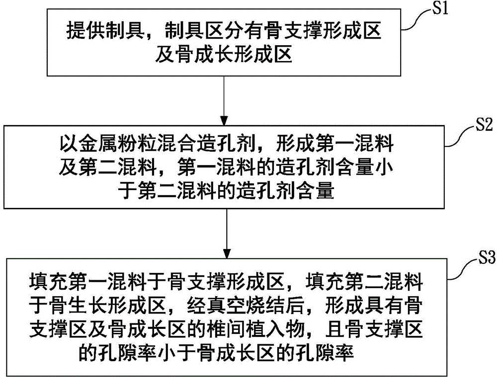
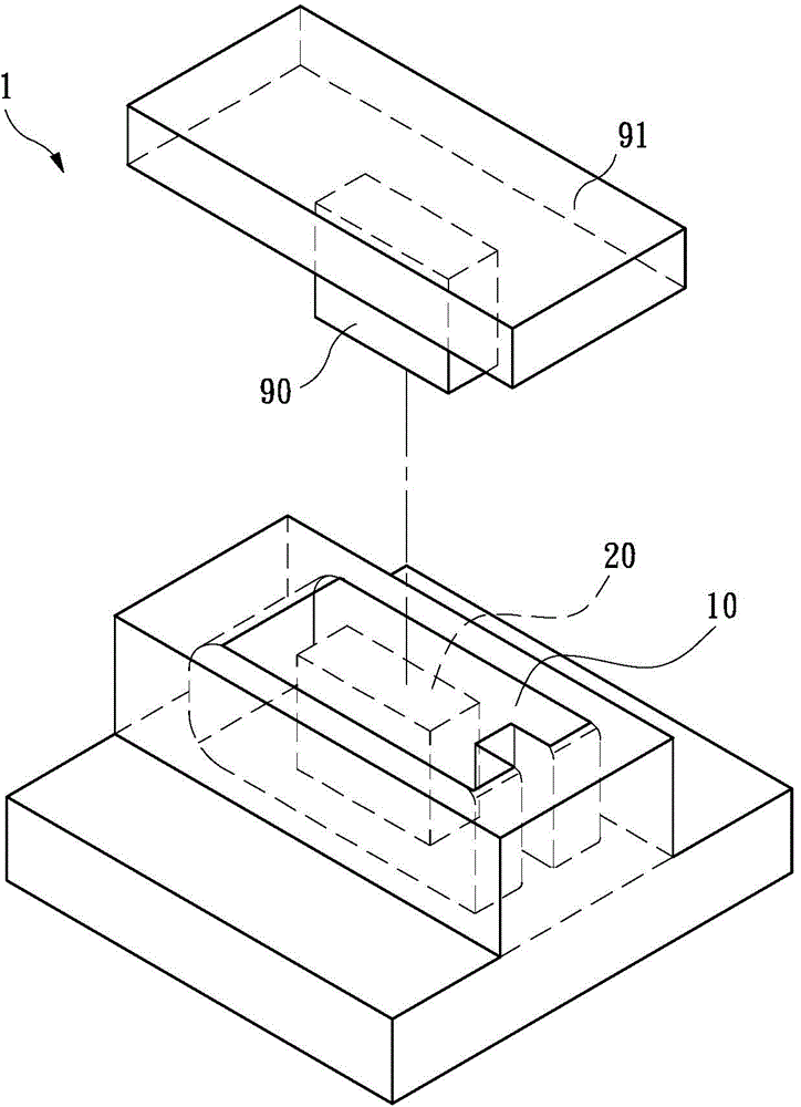
[0051] see figure 1 and figure 2 , figure 1 A flow chart of a manufacturing method of an intervertebral implant according to the present invention, figure 2 An exploded schematic view of a manufacturing method of an intervertebral implant according to the present invention.

[0052] A kind of intervertebral implant of the present invention, its manufacturing method comprises the following steps: firstly, step S1, provides preparation tool 1, and preparation tool 1 zone has bone support formation area 10, bone growth formation area 20, central block 90 and upper cover 91.

[0053] Tool 1 is designed through computer simulation and drawing, according to the required rigid performance, to design the mold of the intervertebral implant.

[0054] The bone gro...


PUM


Abstract

An intervertebral implant is a porous structure formed of a plurality of metal balls, and the intervertebral implant includes a bone support area and a bone growth area. The bone support area and the bone growth area each have a plurality of connecting holes, and a porosity of the bone support area is smaller than that of the bone growth area.

Description

technical field [0001] The invention relates to an intervertebral implant, in particular to an intervertebral implant composed of a plurality of metal spheres with uniform particle diameters, and the intervertebral implant has multiple regions, wherein each region is defined by the metal spheres. The different quantities of components form different porosity and pore size respectively, so that the intervertebral implant has a composite pore structure with multiple rigidities. Background technique [0002] Lumbar interbody fusion, which involves removing a disc from two vertebrae and fusing them together. This procedure is also known as "spinal fusion". It is usually used to treat patients with persistent back pain, sciatica or weakness of legs caused by spinal diseases such as degenerative spondylosis and herniated disc. [0003] The existing intervertebral fusion implants have poor fusion effect and slippage after being implanted into the bone. Therefore, auxiliary treatm...

Claims


Application Information

Patent Timeline
Patent Type & Authority Applications(China)
IPC IPC(8): A61L27/06A61L27/56A61F2/44
CPCA61F2/447A61F2002/30011A61F2002/30593A61F2002/30957A61F2002/30968A61F2310/00011A61F2310/00023A61L27/04A61L27/56A61L2430/38B22F3/10B22F3/1109B22F3/1121B22F5/00B22F7/06C22C1/0458
Inventor 王鍏晴陈彦年苏子可王福山施威任陈维德
Owner METAL INDS RES & DEV CENT
Learn More