Dynamic constant thickness ratio taper control method

A technology of equal thickness and wedge shape, which is applied in the direction of rolling force/roll gap control, etc., can solve the problems of rolling breakage, feedback control lag, rack wave shape, etc. The effect of shaping and rolling

Inactive Publication Date: 2015-06-03
SHANGHAI MEISHAN IRON & STEEL CO LTD
View PDF6 Cites 7 Cited by
  • Summary
  • Abstract
  • Description
  • Claims
  • Application Information

AI Technical Summary

Problems solved by technology

This stepwise adjustment method cannot realize the real-time adjustment of the wedge shape, and there is a serious lag in feedback control. Especially when rolling thin-gauge strip steel, this method cannot accurately and dynamically ensure that the roll gap deviation is adjusted according to the equal thickness ratio, which may easily lead to Shape defects such as unilateral waves and crushing appear at the rack outlet
Furthermore, this method adopts the simultaneous adjustment of the roll gap deviation of each frame. Once there is a deviation at the exit, the roll gap adjustment amount of each frame is calculated at the same time, and the adjustment is carried out at the same time; while we only calculate the adjustment amount of F1. Calculate the adjustment amount of F2 on the basis of the actual adjustment. When each place rolled by F1 reaches F2, F2 will adjust that place accordingly, and then apply the same method to F3, F4, F5, F6, etc., so it is the same Only in this way can we ensure that the adjustment amount of the strip at any place passes through each rolling mill at different times but at the same place to strictly maintain the "equal thickness ratio", so other methods cannot dynamically realize the roll gap of each stand in real time. Equal thickness ratio control of the deviation, which will produce relative waves between the racks

Method used


Image

  • Dynamic constant thickness ratio taper control method
  • Dynamic constant thickness ratio taper control method
  • Dynamic constant thickness ratio taper control method

Examples


Embodiment 1

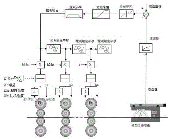
[0017] A dynamic constant thickness ratio wedge control method, as shown in the appendix figure 1 As shown, 1) The real-time wedge value W obtained after the meter at the exit of the finishing mill F7 detects the strip wedge and delays it by 20 meters;

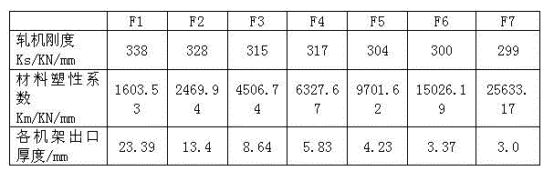
[0018] 2) After filtering, comparing with the reference value, controlling the dead zone and controlling the amplitude limit, the F1 outlet wedge W*H is calculated according to the thickness ratio 1 / H 7 , where H 1 , H 7 is the thickness of F1 and F7 outlet strip steel, so as to calculate the roll gap deviation adjustment amount K / (1+Km of F1 frame 1 / Ks 1 )* W*H 1 / H n *1 / 2, where K is the gain coefficient, generally 0.5-0.8, Km 1 is the plastic deformation coefficient of the F1 frame strip, Ks 1 is the stiffness coefficient of the F1 rolling mill;

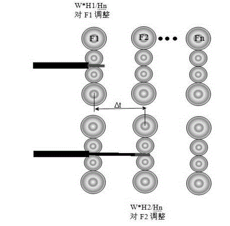
[0019] 3) As attached figure 2 As shown in the figure, when the strip, which has the effect of adjusting the roll gap deviation of the F1 frame by the wedge feedback...


PUM


Abstract

The invention relates to a dynamic constant thickness ratio taper control method, wherein the method comprises the following steps: 1) effectiveness judgment of finish rolling outlet band steel taper measured value; obtaining an actual measurement feedback by methods such as filtering, obtaining the needed control deviation W after comparing with a benchmark; 2) calculation of roll gap deviation value on bilateral sides of F1 rolling mill; 3) calculation of roll gap deviation value on bilateral sides of F2 rolling mill; the calculation of F3 rolling mill is in a similar way; adjusting based on the value which is obtained from real-time memorizing and tracking the roll gap actual adjustment on bilateral sides of the F2 rolling mill. The method has the advantages as follows: 1) the method is simple and easy to operate; 2) the method obviously increases the taper control precision since the application of Meishan steel 1780 hot continuous rolling; the comprehensive taper index of plus or minus 20 microns is increased from 50% in the past to the 90% at present; stable application of rolling thin band steel having a thickness of 2.0mm can also be achieved; not only the taper control precision is increased, but also the stability in plate shape and rolling is ensured.

Description

technical field [0001] The invention relates to a dynamic equal-thickness-ratio wedge-shape control method, in particular to an automatic wedge-shape control technology for hot continuous rolling and finishing rolling. Background technique [0002] As hot strip steel is more and more directly used in automobiles, household appliances and other products, users have put forward higher requirements for the wedge shape of hot rolled strip steel, so as to reduce the same thickness of strip steel when used by downstream users Difference. However, in the actual production process of hot rolling, most manufacturers have not established the wedge-shaped automatic control function. It leads to deviation, unilateral wave, rolling break and even steel scrap in finishing rolling. The paper "A Wedge Control Method for Strip Hot Rolling" also stated that the wedge deviation obtained by the wedge instrument at the exit of the rack can be used to adjust the roll gap deviation of each rack;...

Claims


Application Information

Patent Timeline
Patent Type & Authority Applications(China)
IPC IPC(8): B21B37/58
CPCB21B37/58
Inventor 谢向群
Owner SHANGHAI MEISHAN IRON & STEEL CO LTD
Why Eureka
Try Eureka