An annealing furnace inlet sealing device

An inlet sealing and annealing furnace technology, applied in furnaces, heat treatment furnaces, furnace types, etc., can solve the problems of lack of protective gas recovery device, injury to workers, leakage of protective gas, etc., to prevent serious thermal deformation, save maintenance time, Guaranteed sealing effect

Active Publication Date: 2017-01-18
宝钢日铁汽车板有限公司
View PDF3 Cites 0 Cited by
  • Summary
  • Abstract
  • Description
  • Claims
  • Application Information

AI Technical Summary

Problems solved by technology

[0004] 1) In the production process, since the sealing roller is driven to open and close by the cylinder, the adjustment of the roller gap needs to adjust the stroke of the cylinder during maintenance, which is time-consuming and labor-intensive for the production personnel, and the accuracy is not high
[0005] 2) During the production process, the temperature in the annealing furnace is high, and part of the roller surface of the sealing roller is connected to the furnace, while part of the roller surface is exposed to the ambient temperature. Excessive temperature difference may cause the overall thermal deformation of the roller, especially when the roller stops abnormally. When turning, the deformation is more serious
[0006] 3) Since there is a certain gap between the sealing roller and the furnace shell, although heat insulating materials are provided along the length of the roller to prevent the leakage of gas in the furnace, but there is no shelter in the gap between the two ends of the roller, the leakage of the atmosphere in the furnace more severe at the end of the stick
[0007] 4) A certain amount of protective gas will leak from the sealing rod, and there is no protective gas recovery device. The leaked protective gas in the furnace will cause great harm to the working environment and cause certain bodily harm to the staff

Method used


Image

  • An annealing furnace inlet sealing device
  • An annealing furnace inlet sealing device
  • An annealing furnace inlet sealing device

Examples


Embodiment Construction

[0046] The annealing furnace inlet sealing device according to the present invention will be further explained and illustrated in conjunction with the accompanying drawings and specific embodiments below, but such explanations and illustrations do not constitute improper limitations on the technical solution of the present invention.

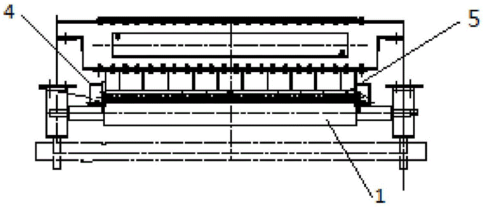
[0047] figure 1 and figure 2 The structures of the annealing furnace entrance sealing device according to the present invention under different viewing angles in one embodiment are shown respectively.

[0048] like figure 1 and figure 2 As shown, the annealing furnace inlet sealing device is provided with a pair of sealing rollers 1, which also includes a sealing roller gap adjustment device 2, a cooling device 3, an end sealing device 4, a sealing roller axial sealing device 5 and a suction pipe 6 .

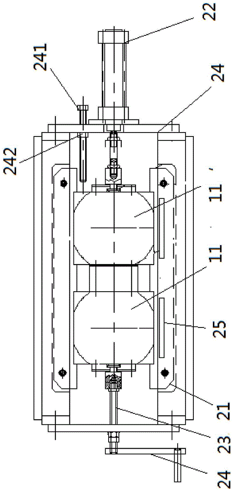
[0049] image 3 It shows the structure of the sealing roll gap adjustment device in the annealing furnace entrance sealing device accordin...


PUM


Abstract

The invention discloses an annealing furnace inlet sealing device. The annealing furnace inlet sealing device comprises at least one pair of sealing roller; besides, the annealing furnace inlet sealing device also comprises a roller gap regulating device, a driving part, a cooling device, end part sealing devices, a sealing plate and a sealing roller axially-sealing device, wherein the roller gap regulating device comprises guide rails; bearing seats of the sealing rollers are in sliding connection with the guide rails; the length direction of the guide rails is the same as the extension direction of the distance between the two sealing rollers; the driving part is correspondingly fixedly connected with the bearing seat of each sealing roller and is used for driving each bearing seat to slide along the guide rail; the cooling device is arranged above the sealing rollers and arranged on a shell of an annealing furnace; the cooling device comprises at least one water tank provided with a water inlet and a water outlet; flow guiding plates staggered up and down are arranged inside the water tank; the end part sealing devices are arranged at an axial end parts of the sealing rollers; each end part sealing device comprises a sealing plate which is arranged vertical to the axial direction of the sealing rollers; the sealing roller axially-sealing device is arranged between the sealing rollers and the shell of the annealing furnace along the axial direction of the sealing rollers.

Description

technical field [0001] The invention relates to a sealing device, in particular to a sealing device for an annealing unit. Background technique [0002] As an important equipment of the annealing unit, the airtightness of the annealing furnace is directly related to the final quality of the steel product. At the same time, the working environment of the annealing unit also depends on the airtightness of the annealing furnace. Usually, the strip steel after the entrance cleaning enters the furnace through the turning roll for heating, and the airtightness at the entrance of the annealing furnace is particularly important. The entrance of the existing annealing furnace generally uses a pair of openable and closable sealing rollers to seal the gas in the furnace. The degree of leakage, that is, the degree of sealing of the annealing furnace has the most direct impact. The function of setting the sealing device at the annealing unit is to reduce the leakage of the protective g...

Claims


Application Information

Patent Timeline
Patent Type & Authority Patents(China)
IPC IPC(8): C21D1/26C21D9/54
CPCC21D1/26C21D9/0006C21D9/54
Inventor 强晓彬王鲁顾希成
Owner 宝钢日铁汽车板有限公司
Why Eureka
Try Eureka