
Etching machine

An etching machine and etching tank technology, applied in the field of etching machines, can solve the problems of slow corrosion speed and uneven corrosion, and achieve the effects of accelerating corrosion speed, improving corrosion uniformity, and improving corrosion uniformity and corrosion speed

Active Publication Date: 2015-06-03
菏泽力芯电子科技有限公司
View PDF2 Cites 7 Cited by
  • Summary
  • Abstract
  • Description
  • Claims
  • Application Information

AI Technical Summary

Problems solved by technology

[0004] In view of this, the present invention proposes an etching machine to solve the problems of uneven corrosion and slow corrosion speed

Method used


Image

  • Etching machine
  • Etching machine
  • Etching machine

Examples


Embodiment Construction

[0026] It should be noted that, in the case of no conflict, the embodiments of the present invention and the features in the embodiments can be combined with each other. The present invention will be described in detail below with reference to the accompanying drawings and examples.

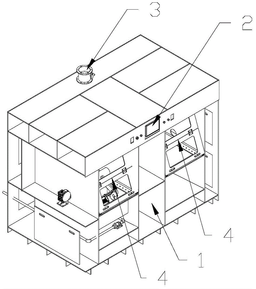
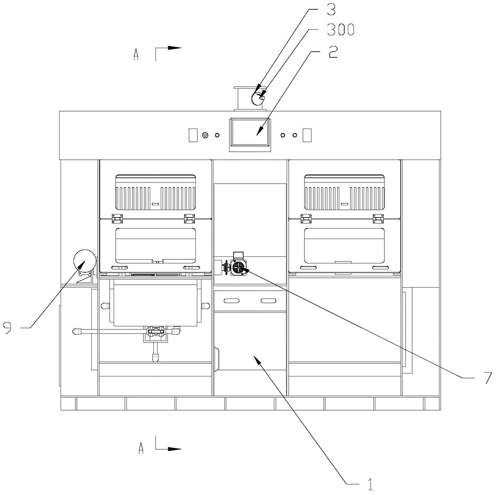
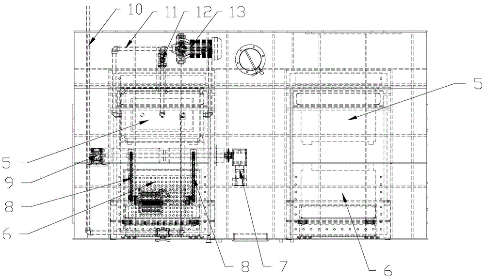
[0027] Combine below Figure 1 to Figure 6 , the preferred embodiment of the present invention is described in further detail,

[0028] like figure 1 and image 3 As shown, an etching machine is provided with two etching tanks 5, two flushing tanks 6 and two driving devices in the cabinet 1, and the two etching tanks 5, two flushing tanks 6 and two driving devices are arranged left and right, The two etching grooves 5 and the two flushing grooves 6 are arranged one after the other, and the two driving devices are respectively located between the two etching grooves 5 and the two flushing grooves 6 . like figure 1 and figure 2 As shown, a controller 2 and an exhaust system 3 are also instal...


PUM

PropertyMeasurementUnit
diameteraaaaaaaaaa

Abstract

The invention discloses an etching machine, wherein an etching groove, a flushing tank and a driving device are arranged in a chassis; a basket is connected to the driving device, a first rotary shaft and a second rotary shaft are arranged on the basket, and the driving device drives the basket to rotate around the first rotary shaft and drives the first rotary shaft to rotate around the second rotary shaft. The etching machine disclosed by the invention improves the corrosive uniformity and corrosive speed as well as the uniformity of backwashing and the flushing speed.

Description

technical field [0001] The invention relates to an etching device for electronic components, in particular to an etching machine. Background technique [0002] Etching machines can be divided into chemical etching machines and electrolytic etching machines. In chemical etching, chemical solutions are used to achieve the purpose of etching through chemical reactions. Chemical etching is the technique of removing material by chemical reaction or physical impact. Etching machines are commonly used in fields such as silicon wafers, semiconductors, circuit boards, metal products, etc. [0003] At present, the automatic chemical etching machines seen on the market use high-pressure spraying and etched linear motion to form a continuous and uninterrupted feeding state to corrode the work to improve production efficiency, but the corrosion is uneven, the pass rate is low, and the corrosion rate is high. slow. In addition, there is another kind of etching machine, which generally ...

Claims


Application Information

Patent Timeline
Patent Type & Authority Applications(China)
IPC IPC(8): C23F1/08
Inventor 裴文龙
Owner 菏泽力芯电子科技有限公司
Learn More