
Hydraulic type directional fracturing equipment

A directional fracturing and hydraulic technology, applied in hydraulic mining, earth-moving drilling, special mining, etc., can solve problems such as drilling damage, affecting mining progress, drilling, etc., and achieve uniform force on the cylinder head, which is conducive to popularization and implementation. , the effect of long service life

Inactive Publication Date: 2015-06-03
张弘
View PDF5 Cites 2 Cited by
  • Summary
  • Abstract
  • Description
  • Claims
  • Application Information

AI Technical Summary

Problems solved by technology

There are many disadvantages in this method. First, the sealing problem after the high-pressure water gun is inserted into the drill hole cannot be solved well. It needs very tedious fixing work to firmly seal and fix the high-pressure water gun on the orifice. There are still two common problems in this way. One is that it takes a long time to seal and fix, which affects the mining progress, and the other is that the sealed and fixed structure is still not firm, and the water gun often breaks away after the water pressure increases, causing the drill hole to be destroyed and re-drilled. Even cause the coal seam around the borehole to outburst
Another disadvantage of the way of using high-pressure water guns is that it will inevitably cause problems such as water accumulation in the mining environment, which will affect further mining operations.

Method used


Image

  • Hydraulic type directional fracturing equipment
  • Hydraulic type directional fracturing equipment
  • Hydraulic type directional fracturing equipment

Examples


Embodiment Construction

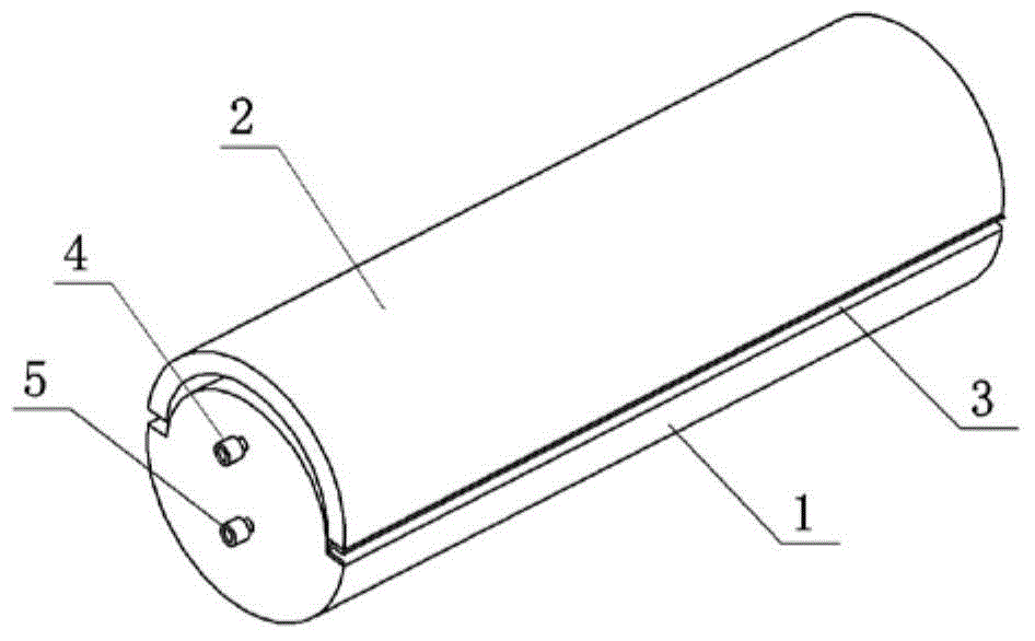
[0011] join figure 1 , the hydraulic directional fracturing equipment includes a horizontal cylinder body 1 and a cylinder head 2, the cylinder body 1 and the cylinder head 2 form a cylindrical structure. All the joint surfaces between the cylinder head 2 and the cylinder body 1 are sealed 3 with a flexible connection layer. Between the cylinder head 2 and the cylinder body 1 are provided an upper stepped surface and a lower stepped surface 7 which cooperate with each other. The flexible connection layer 3 is arranged between the upper and lower step surfaces.

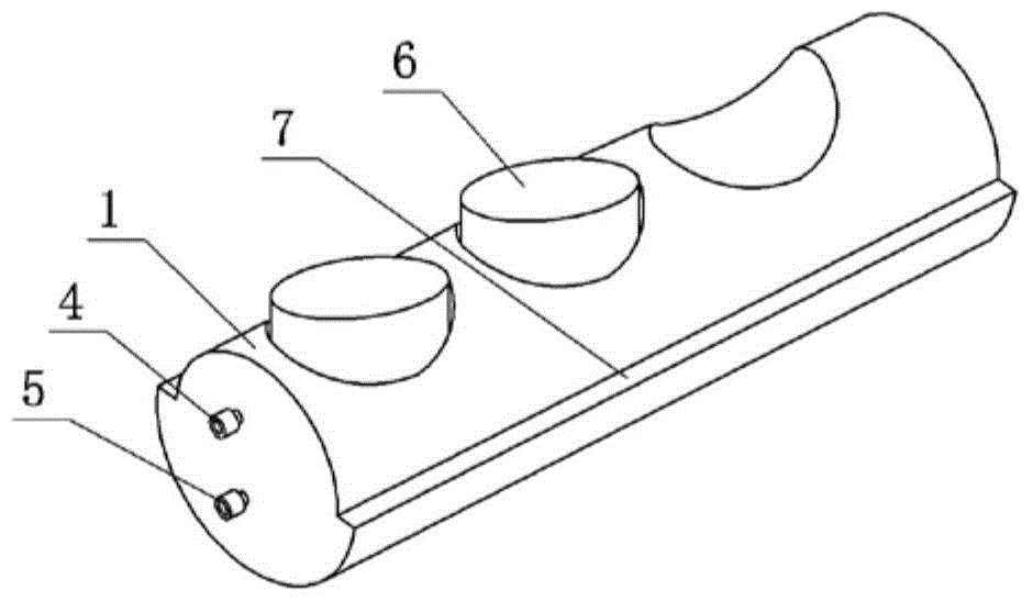
[0012] join figure 2 : A plunger hole is arranged radially on the side opposite to the cylinder body 1 and the cylinder head 2, and plungers 6 are installed respectively. The orifice of the plunger hole is provided with a sealing structure to prevent the plunger from being pulled out. The upper end of the plunger 6 is connected to the inner wall of the cylinder head 2 .

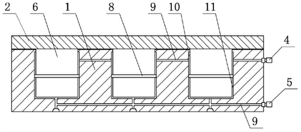
[0013] join image 3 : The middle sectio...


PUM


Abstract

The invention discloses hydraulic type directional fracturing equipment. A cylinder body and a cylinder cover form a cylindrical structure; plunger holes are formed at one side of the cylinder body along the radial direction and plungers are arranged in the plunger hole; a circular flange in seal fit with the inner wall of each plunger hole is arranged at the middle section of each plunger; and the upper side of each circular flange is provided with an upper oil chamber, and the lower side of each circular flange is provided with a lower oil chamber. The cylinder body and the cylinder cover of the equipment disclosed by the invention are combined together to form the cylindrical structure which can be just arranged in a borehole inner wall, and is convenient to mount and good in fit property. The unfolded cylinder body and cylinder cover can provide a maximum thrust stroke, multiple plungers work at the same time to apply pressure uniformly to the inner wall of the cylinder cover, and the cylinder cover is uniformly stressed and is very high in strength. A flexibly connection layer ensures that the cylinder body is completely sealed with the cylinder cover, so that damages caused by severe environments to a hydraulic system can be avoided. The equipment is convenient to use, is efficient, high in strength, good in effect and long in service life, and is very beneficial for popularization and implementation.

Description

technical field [0001] The invention relates to an auxiliary tool for coal mine exploitation, in particular to a hydraulic directional fracturing equipment. Background technique [0002] In the current coal mining process, it is necessary to drill holes in the coal seam with a drilling tool, then use a high-pressure water gun to draw water into the hole, and use the pressure of the high-pressure water gun to crack the hole wall in the drill hole for further mining. There are many disadvantages in this method. First, the sealing problem after the high-pressure water gun is inserted into the drill hole cannot be solved well. It takes very tedious fixing work to securely seal the high-pressure water gun to the orifice. There are still two common problems in this way. One is that it takes a long time to seal and fix, which affects the mining progress, and the other is that the sealed and fixed structure is still not firm, and the water gun often breaks away after the water press...

Claims


Application Information

Patent Timeline
IPC IPC(8): E21C45/00
CPCE21C45/00
Inventor 张弘
Owner 张弘
Learn More