
Engaging rubber joint and method of making the same
A technology of rubber joints and manufacturing methods, which is applied to springs, springs, shock absorbers, etc. made of plastic materials, can solve problems such as failure to meet vibration reduction requirements, short service life, and large stiffness adjustment range, and achieve increased thickness Adjust the space and compression displacement, simplify the structure, and adjust the effect of a large range
- Summary
- Abstract
- Description
- Claims
- Application Information
AI Technical Summary
Problems solved by technology
Method used
Image

Examples
Embodiment Construction
[0026] Embodiments of the present invention will be described in detail below in conjunction with the accompanying drawings.
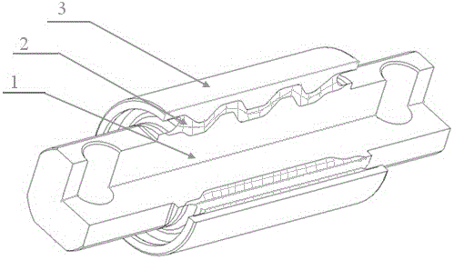
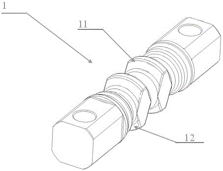
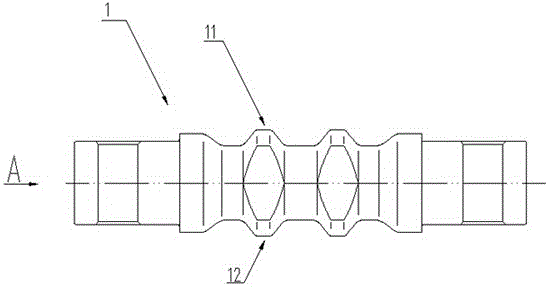
[0027] Such as Figure 1 to Figure 7 As shown, the meshing rubber joint includes a mandrel 1, an elastic rubber body 2 and a metal jacket 3, the mandrel 1, the elastic rubber body 2 and the jacket 3 are integrally vulcanized together, and the shaft wall of the mandrel 1 is provided with a The upper protrusion 11 and the lower protrusion 12 distributed in the circumferential direction of the mandrel 1 and having the same shape and size, the upper protrusion 11 and the lower protrusion 12 are symmetrically arranged up and down with respect to the central axis of the mandrel 1, The upper protrusions 11 and the lower protrusions 12 are uniformly distributed along the axial direction of the mandrel 1, and the width of the upper protrusions 11 along the radial direction of the mandrel 1 is less than or equal to the The diameter of the middle part of the man...
PUM
 Abstract
Description
Claims
Application Information