
Diaphragm assembly

A component and diaphragm technology, applied in the direction of pipe components, pipes/pipe joints/fittings, mechanical equipment, etc., can solve problems such as combustion and explosion

Inactive Publication Date: 2015-06-03
SHANGHAI AEROSPACE SYST ENG INST
View PDF7 Cites 2 Cited by
  • Summary
  • Abstract
  • Description
  • Claims
  • Application Information

AI Technical Summary

Problems solved by technology

The invention adopts the technical scheme of using pure copper diaphragm to solve the inherent defect that the existing diaphragm assembly will burn and explode when working under high temperature and high velocity oxygen, and has anti-installation reverse design, thereby improving the adaptability and reliability of the diaphragm assembly ,safety

Method used


Image

  • Diaphragm assembly

Examples


Embodiment Construction

[0016] The invention will be described in more detail hereinafter with reference to the accompanying drawings showing embodiments of the invention. However, this invention may be embodied in many different forms and should not be construed as limited to the embodiments set forth herein. Rather, these embodiments are provided so that this disclosure will be thorough and complete, and will fully convey the scope of the invention to those skilled in the art. In these drawings, the size and relative sizes of layers and regions may be exaggerated for clarity.

[0017] Now, the present invention will be further explained by describing preferred specific embodiments according to the present invention in detail.

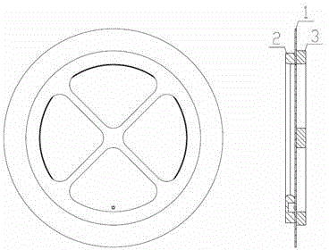
[0018] figure 1 Shown is a schematic structural diagram of a diaphragm assembly of the present invention, which includes a rupture diaphragm 1 , a gasket 2 , and a grille 3 . The outer diameter of the gasket 2 is smaller than the outer diameter of the barrier 3, and a squ...


PUM


Abstract

The invention relates to a diaphragm assembly. The diaphragm assembly comprises a rupture diaphragm, a gasket and a grate. The outer diameter of the gasket is smaller than that of the grate. The gasket is designed with a blind hole. The rupture diaphragm is designed with a protrusion block. When the diaphragm assembly is assembled, the protrusion block on the rupture diaphragm is embedded into the blind hole of the gasket, and one side provided with a nick, of the rupture diaphragm is fitted to the grate. When the diaphragm assembly is mounted, the grate is connected to a flange on the upstream side of the air flow. The diaphragm assembly is made of a pure copper diaphragm and accordingly has good compatibility with high-temperature and high-speed oxygen. The fail-proof design is used for ensuring that the rupture diaphragm is not mounted reversely when the diaphragm assembly is assembled and the diaphragm assembly is not reversely mounted in a pipe.

Description

[0001] technical field [0002] The invention relates to a diaphragm assembly, in particular to a diaphragm assembly used for self-generated pressurization of a liquid oxygen storage tank of a launch vehicle. [0003] Background technique [0004] The diaphragm assembly is an important stand-alone unit used in the pressurized delivery system of the launch vehicle. Its function is to separate the liquid oxygen storage tank from the pressurization system by means of the diaphragm assembly before the engine starts. The disc ruptures, pressurizing the tank. [0005] In the known diaphragm assembly used in the existing pressurized conveying system, the material of the ruptured diaphragm in the diaphragm assembly is pure aluminum plate, and there are hidden dangers of sparks and deflagration in the pure aluminum diaphragm under high temperature and high speed oxygen scour. [0006] In the diaphragm assembly, the side of the grille and gasket in contact with the ruptured diaph...

Claims


Application Information

Patent Timeline
Patent Type & Authority Applications(China)
IPC IPC(8): F16L55/00
CPCF16L55/00
Inventor 宿彩虹张亮陈其法周遇仁石玉鹏赵永立
Owner SHANGHAI AEROSPACE SYST ENG INST
Learn More