
Dual-hydraulic cylinder driven hydraulic locking shaft sleeve performance testing platform

A technology of dual hydraulic cylinders and a test platform, which is applied in the field of hydraulic control, can solve problems such as shaft sleeve fatigue cracks, and achieve the effects of energy saving, material saving, and simple operation

Inactive Publication Date: 2015-06-03
SHENYANG POLYTECHNIC UNIV
View PDF6 Cites 2 Cited by
  • Summary
  • Abstract
  • Description
  • Claims
  • Application Information

AI Technical Summary

Problems solved by technology

The locking torque of the hydraulic locking sleeve is not only related to the pressure of the hydraulic oil, but also closely related to the structural size (diameter, length, thickness) and processing quality (surface roughness, coaxiality, fit clearance) of the sleeve and other factors. Related, in addition, the relative movement of the shaft and the bushing produces friction and wear, frequent locking and loosening actions are likely to cause fatigue cracks in the bushing, and the service life and reliability of the bushing also need to be verified by tests. For this reason, it is necessary to invent hydraulic pressure Performance testing test platform for locking bushing
Chinese utility model patent 211421064123.10 proposes a performance and reliability test platform for hydraulic locking bushings, but only one size bushing can be tested. Changing a bushing size requires a lot of manpower and material resources to reprocess A set of parts, for which it is necessary to invent a performance and reliability test platform for hydraulic locking bushings with a simple structure that can meet different sizes

Method used


Image

  • Dual-hydraulic cylinder driven hydraulic locking shaft sleeve performance testing platform
  • Dual-hydraulic cylinder driven hydraulic locking shaft sleeve performance testing platform
  • Dual-hydraulic cylinder driven hydraulic locking shaft sleeve performance testing platform

Examples


specific Embodiment approach

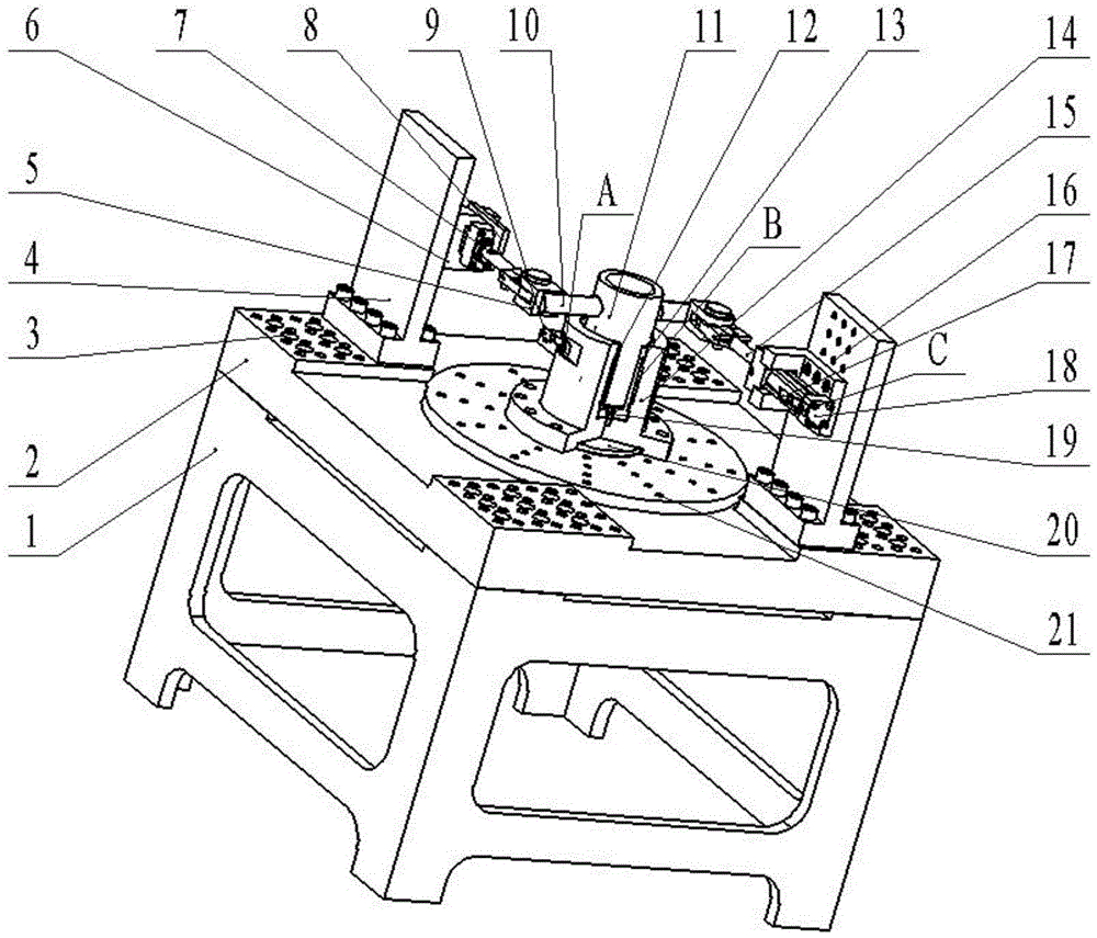
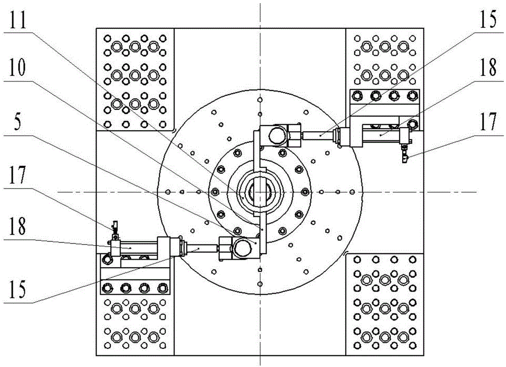
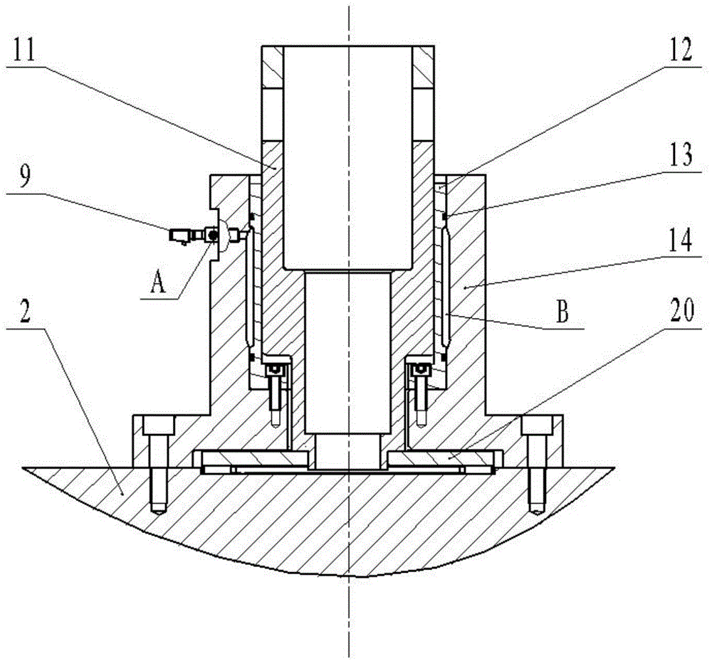
[0032] like figure 1 As shown, the present invention provides a dual-hydraulic cylinder-driven hydraulic locking bushing performance test platform, which is characterized in that: the platform mainly includes a support 1, a mounting table 2, a hydraulic cylinder bracket position adjustment pin hole 3, and a hydraulic cylinder bracket 4 And hydraulic cylinder, hydraulic cylinder bracket 6, travel switch contact 7, travel switch 8, electronic display pressure gauge 9, torsion bar 10, rotating shaft 11, hydraulic locking sleeve 12, O-ring 13, hydraulic locking shaft Sleeve 14, hydraulic cylinder bracket height adjustment screw hole 16, electronic display pressure gauge 17, hydraulic cylinder block 18, hydraulic locking sleeve fixing screw 19, thrust bearing 20, flange screw hole 21, pressure oil chamber inlet and outlet A. Pressure oil cavity B, hydraulic cylinder push stroke inlet and outlet port C and hydraulic cylinder return stroke inlet and outlet port D.

[0033] The inst...


PUM


Abstract

The invention provides a dual-hydraulic cylinder driven hydraulic locking shaft sleeve performance testing platform, which mainly comprises a support, a mounting table, a hydraulic cylinder bracket and hydraulic cylinders. The platform has the main advantages that (1) twisting couple moment can be maximally provided, so that energy consumption is reduced, and the phenomenon of motor damage caused by excessively high power when a motor is used as a driver is avoided; (2) the distance between the axial lines of rods of the two hydraulic cylinders can be conveniently regulated, so that the requirements of different torque output can be flexibly met; (3) the heights of the hydraulic cylinders can be conveniently regulated, so that the performance testing requirements of hydraulic locking shaft sleeves with different lengths can be flexibly met; (4) the mounting requirements of hydraulic locking shaft sleeves with various sizes and hydraulic locking shaft sleeve seats can be met, and when the hydraulic locking shaft sleeves with different sizes are tested, only the hydraulic locking shaft sleeve seats and rotating shafts are required to be replaced, so that materials are saved, and simplicity in operation is ensured.

Description

technical field [0001] The invention belongs to the field of hydraulic control, and relates to a performance test platform for locking and positioning components of rotating shaft parts, in particular to a double hydraulic cylinder-driven hydraulic locking system for testing the locking torque of hydraulic locking sleeves Shaft sleeve performance test platform. Background technique [0002] In engineering applications, rotating shaft parts are widely used. The rotating braking and positioning locking performance of rotating shaft parts sometimes determine the performance of the overall mechanical equipment. Positioning and locking performance is particularly important. Five-axis linkage Take CNC machine tools as an example: five-axis linkage CNC machine tools are composed of three linear feed axes and two rotary feed axes. Processing also needs to be able to complete processing in a specific direction and angle, which requires that the rotation (or swing) has the functions ...

Claims


Application Information

Patent Timeline
Patent Type & Authority Applications(China)
IPC IPC(8): G01M13/00
Inventor 闫明王乾勋金昊刘栋孙淑霞
Owner SHENYANG POLYTECHNIC UNIV
Learn More