[0023] Hereinafter, the present disclosure will be described more fully with reference to the accompanying drawings, in which exemplary embodiments of the inventive concept are shown.
[0024] As those skilled in the art will recognize, the described embodiments may be modified in various different ways without departing from the spirit or scope of the present disclosure.
[0025] In the description of the present disclosure, parts irrelevant to the description will be omitted. Throughout the specification, the same reference numerals generally refer to the same elements.
[0026] In addition, for better understanding and ease of description, the size and thickness of each configuration shown in the drawings are arbitrarily shown, but the present disclosure is not limited thereto. In the drawings, the thickness of layers, films, panels, regions, etc., are exaggerated for clarity.
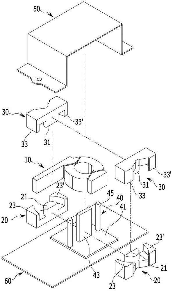
[0027] figure 1 It is an exploded perspective view showing a transformer according to an exemplary embodiment of the present disclosure.
[0028] Such as figure 1 As shown, a transformer according to an exemplary embodiment of the present disclosure includes a hollow-shaped bobbin 10 wound with a primary coil and a secondary coil. The combination of a pair of upper cores 30 and a pair of lower cores 20 surrounds the inside and outside of the bobbin 10 on its upper and lower sides. The heat dissipation plate 40 is provided between the pair of upper cores 30 and the pair of lower cores 20.
[0029] The lower core 20 includes a lower body portion 21 and a pair of lower wing portions 23, 23', which are provided at the center of the bobbin 10, the pair of lower wing portions are connected to the lower body portion 21 and surround the outside of the bobbin 10.
[0030] The upper core 30 includes an upper body portion 31 and a pair of upper wing portions 33, 33', which are provided at the center of the bobbin 10, the pair of upper wing portions are connected to the upper body portion 31 and surround the outside of the bobbin 10.
[0031] The upper body portion 31 and the pair of upper wing portions 33, 33' and the lower body portion 21 and the pair of lower wing portions 23, 23' are combined at the upper and lower sides of the bobbin 10, respectively. The pair of upper wing portions 33, 33' and the pair of lower wing portions 23, 23' are combined in the up-down direction. At this time, the spool 10 is disposed at a space formed by combining the upper core 30 and the lower core 20, and the upper core 30 and the lower core 20 surround the inside and the outside of the spool 10.
[0032] The bobbin 10 is formed in a hollow shape and made of an insulating material. The primary coil is wound on the outside of the bobbin 10, and the secondary coil is wound on the outside of the primary coil. The insulating material is provided between the primary coil and the secondary coil, thereby insulating the primary coil from the secondary coil.
[0033] The lower core 20 and the upper core 30 are made of a magnetic substance.
[0034] When AC current flows through the primary coil wound around the bobbin 10, a magnetic flux is generated adjacent to the primary coil (between the lower body portion 21 and the upper body portion 31). At this time, the magnetic flux is generated adjacent to the secondary coil (between the lower wing portion and the upper wing portion) in a direction that interferes with the change of the magnetic flux generated by the primary coil. Therefore, current flows through the generation of induced electromotive force.
[0035] The heat dissipation plate 40 includes a bottom plate 41 and an extension plate, the bottom plate is mounted to the housing 60 of the transformer, and the extension plate extends upward from the bottom plate 41. The extension plate includes a central plate 43 and a pair of side plates 45 which are provided at opposite sides of the central plate 43. The pair of side plates 45 are separated from the center plate 43.
[0036] The bottom surfaces of the pair of lower cores 20 are mounted to the bottom plate 41, and the lower body portions 21 of the pair of lower cores 20 are coupled to the center plate 43. The lower wing portions 23, 23' of the pair of lower cores 20 are joined to the pair of side plates 45.
[0037] The upper body portion 31 of the pair of upper cores 30 is joined to the central plate 43, and the upper wing portions 33, 33' of the pair of upper cores 30 are joined to the pair of side plates 45.
[0038] At this time, thermal grease is applied between the pair of upper body parts 31 and the central plate 43, between the pair of lower body parts 21 and the central plate 43, and applied to the pair of upper wing parts 33, 33' and the side Between the plates 45 and applied between the pair of lower wing portions 23, 23' and the side plates 45. Because thermal grease is applied between the core and the heat dissipation plate 40, the heat generated from the core is smoothly transferred to the heat dissipation plate 40 and discharged to the outside.
[0039] The pair of upper core portions 30 and the pair of lower core portions 20 are formed symmetrically based on the center plate 43 and the side plates 45.
[0040] The bobbin 10 is inserted in the space formed between the center plate 43 and the pair of side plates 45.
[0041] Since the heat dissipation plate 40 is provided between the pair of upper cores 30 and the pair of lower cores 20, the heat generated from the cores 20 and 30 can be smoothly discharged to the outside.
[0042] The heat generated from the cores 20 and 30 is smoothly discharged to the outside, and therefore, the overall volume of the cores 20 and 30 can be reduced.
[0043] Moreover, because the heat dissipation plate 40 is disposed between the pair of upper core portions 30 and the pair of lower core portions 20, the volume corresponding to the thickness of the heat dissipation plate 40 can be reduced. As described above, the heat dissipation plate 40 is provided between the pair of upper cores 30 and the pair of lower cores 20, so that the overall volume of the cores 20 and 30 can be reduced.
[0044] Hereinafter, an assembly process of the heat dissipation structure of the transformer according to the exemplary embodiment of the present disclosure will be described. Figure 2 to 5 It is a schematic diagram showing the assembly process of the transformer according to the exemplary embodiment of the present disclosure.
[0045] Such as figure 2 As shown, the pair of lower cores 20 are mounted to the bottom plate 41 of the heat dissipation plate 40. The lower body portion 21 is combined at the opposite side of the center plate 43, and the lower wing portions 23, 23' are combined at the opposite side of the pair of side plates 45. At this time, after the thermal grease is applied between the pair of lower cores 20 and the heat dissipation plate 40, the pair of lower cores are combined with the heat dissipation plate. The heat generated from the combination of the lower core and the upper core can be smoothly transferred to the heat dissipation plate 40 through the thermal grease, thereby improving heat radiation.
[0046] Such as image 3 As shown, the spool 10 is inserted into the space formed between the central plate 43 and the pair of side plates 45.
[0047] Such as Figure 4 As shown, the upper body portion 31 is combined at the opposite side of the central plate 43, and the upper wing portions 33, 33' are combined at the opposite side of the pair of side plates 45. At this time, the pair of upper cores 30 are joined to the pair of lower cores 20, so that the spool 10 is disposed on the pair of lower body portions 21/the pair of upper body portions 31 and the pair of lower wing portions 23, 23'/the Between the upper wing parts 33 and 33'.
[0048] In addition, after the thermal grease is applied between the pair of upper cores 30 and the heat dissipation plate 40, the pair of upper cores 30 and the heat dissipation plate 40 are combined. The heat generated from the core can be smoothly transferred to the heat dissipation plate 40 through the thermal grease, thereby improving heat radiation.
[0049] Such as Figure 5 As shown, the components of the transformer are fixed to the housing 60 by a clamp 50.
[0050] According to the exemplary embodiment of the present disclosure, the heat generated inside the core may be effectively discharged to the outside by providing a heat dissipation plate at the center of the pair of cores.
[0051] Moreover, since tanks and molding liquid are not used, the manufacturing cost of the transformer can be reduced.
[0052] Although the present disclosure has been described in connection with what is currently considered to be actual exemplary embodiments, it should be understood that the present invention is not limited to the disclosed embodiments, on the contrary, it is intended to cover the spirit and spirit contained in the appended claims. Various modifications and equivalent devices within the scope.