
Adaptive variable load anti-islanding method for distributed type photovoltaic power supply

A distributed photovoltaic and anti-islanding technology, applied in the direction of measuring electrical variables, measuring electricity, electrical components, etc., can solve problems such as operating overvoltage hazards, destroying active power balance, and time delay, achieving high accuracy, strong practicability, and The effect of small blind spots

Active Publication Date: 2015-06-03
NANJING NENGDI ELECTRICAL TECH
View PDF11 Cites 6 Cited by
  • Summary
  • Abstract
  • Description
  • Claims
  • Application Information

AI Technical Summary

Problems solved by technology

[0004] However, the existing low-voltage anti-islanding devices still have some disadvantages: (1) When the value of the input capacitive load or inductive load is relatively small, the voltage phase may change slightly, and the change value that is too small will cause the inverter to monitor It is difficult for the device to detect this change, and even if it detects this change, it may not act because it does not exceed the inverter voltage phase change threshold, that is, there is a passive detection blind zone
(2) The existing low-voltage anti-islanding device has not realized the communication connection with the main network, and lacks initiative; if automatic access to the resistive load is adopted at regular intervals, although the access to the resistive load changes the load characteristics, it has no effect on normal operation , only when the resistive load is re-introduced after the island is formed, the active power balance will be destroyed, and the inverter will stop working; however, frequent switching of switches will cause hidden dangers of operating overvoltage, and frequent switching operations will also bring time delays, switch aging, etc. question
However, the complexity of this technical solution is relatively high, and it needs to combine multiple algorithms for detection

Method used

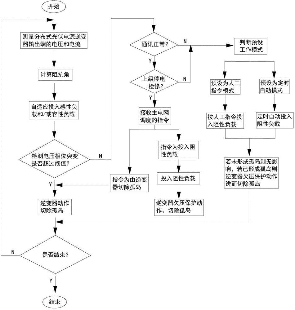

Image

  • Adaptive variable load anti-islanding method for distributed type photovoltaic power supply
  • Adaptive variable load anti-islanding method for distributed type photovoltaic power supply
  • Adaptive variable load anti-islanding method for distributed type photovoltaic power supply

Examples


Embodiment

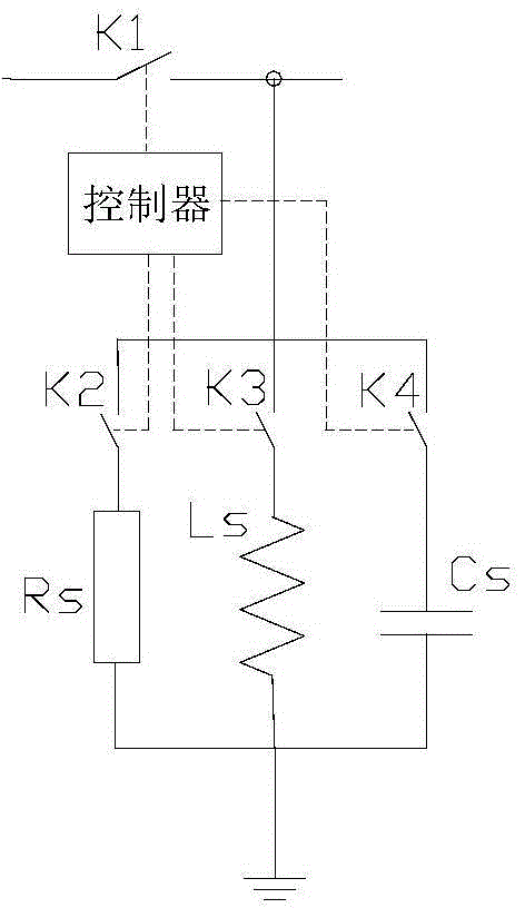
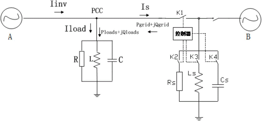
[0036] The self-adaptive anti-islanding device used in this embodiment is as follows: figure 2 As shown, including the controller, main switch K1, resistive load R connected in series S And the resistive load switch K2, the inductive load L connected in series S And the inductive load switch K3, the capacitive load C connected in series S and capacitive load switch K4; one end of the main switch K1 is the input end of the whole device, and the other end of the main switch K1 is separated from the resistive load switch K2 away from the resistive load R S One end of the inductive load switch K3 is far away from the inductive load L S One end of the capacitive load switch K4 is far away from the capacitive load C S Connected at one end, the resistive load R S One end away from the resistive load switch K2, the inductive load L S One end away from the inductive load switch K3, the capacitive load C S The ends away from the capacitive load switch K4 are respectively grounded...


PUM


Abstract

The invention relates to an adaptive variable load anti-islanding method for a distributed type photovoltaic power supply. In the method, an adaptive anti-islanding device is adopted. The method comprises the following steps: performing initialization; calculating an impedance angle phi, and adaptively adjusting the impedance angle to enable the impedance angle to be separated from an island non-detection zone; detecting the island, and cutting off the island. On the basis of acquiring all parameters of the distributed type photovoltaic power supply, the adaptive variable load anti-islanding method can be used for exquisitely judging whether the distributed type photovoltaic power supply generates the island and quickly enabling an inverter to operate after the island formation is determined so as to precisely cut off the island; the whole method is small in dead zone, high in precision, high in practicability, simple and feasible.

Description

technical field [0001] The invention relates to an adaptive variable load anti-islanding method for distributed photovoltaic power sources, and belongs to the technical field of secondary protection for distributed power generation in power systems. Background technique [0002] As far as the applicant knows, anti-islanding protection is an essential function when the distributed power generation system is connected to the grid. When the power supply of the distribution network trips due to a fault accident or blackout maintenance, if the distributed photovoltaic power grid-connected power generation system (such as: photovoltaic power generation, wind power generation, fuel cell power generation, etc.) at each user end fails to detect the power failure state in time, then It is unable to cut itself off from the mains network in time, and eventually forms a self-sufficient power supply island composed of the distributed photovoltaic power grid-connected power generation syst...

Claims


Application Information

Patent Timeline
IPC IPC(8): H02H7/22G01R31/00
Inventor 陈晓宇杨晨悦许平王剑
Owner NANJING NENGDI ELECTRICAL TECH
Learn More