
A charging circuit for a screwdriver

A charging circuit and screwdriver technology, which is applied in the direction of circuits, circuit devices, battery circuit devices, etc., can solve the problems of insufficient connection, inconvenient battery replacement, and short use time, and achieve reliable contact, smooth plugging and unplugging, and improved stability. Effect

Active Publication Date: 2016-11-02
苏州小易科技有限公司
View PDF5 Cites 0 Cited by
  • Summary
  • Abstract
  • Description
  • Claims
  • Application Information

AI Technical Summary

Problems solved by technology

[0003] Traditional electric screwdrivers are generally powered by batteries, but battery replacement is inconvenient and the use time is short
[0004] In the prior art, a rechargeable electric screwdriver generally needs a special charging stand, and the charging stand is generally contact or plug-in, and the connection between the contact charging stand and the electric screwdriver is not compact enough and easy to loosen. It is inconvenient to take off and plug in

Method used


Image

  • A charging circuit for a screwdriver
  • A charging circuit for a screwdriver
  • A charging circuit for a screwdriver

Examples


Embodiment Construction

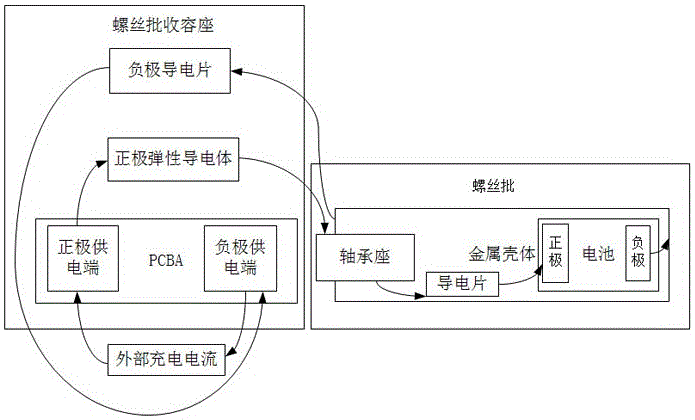
[0032] The invention provides a charging circuit for a screwdriver, such as Figure 1 to Figure 4 As shown, it includes a screwdriver and a screwdriver holder for charging the screwdriver. The screwdriver includes a metal shell 1 and a screwdriver head located at the end of the metal shell 1. The screwdriver head is located at the end of the metal shell 1. , the metal shell 1 is provided with a bearing seat 2, a conductive sheet 3 and a battery 4, the bearing seat 2 is arranged at the end of the metal shell 1 and has an exposed part 21 exposed to the outside of the metal shell, one end of the conductive sheet 3 is connected to the bearing seat 2 are conductively connected, the other end is conductively connected with the positive pole 41 of the battery 4, and the metal shell 1 is conductively connected with the negative pole 42 of the battery 4; the screwdriver receiving seat includes a receiving seat main body 5 and a PCBA6 arranged in the receiving seat main body 5 , PCBA6 h...


PUM


Abstract

The invention discloses a charging loop of a screwdriver. The screwdriver comprises a metal casing, wherein a bearing seat, a conducting strip and a battery are arranged in the metal casing; a screwdriver accommodating seat comprises an accommodating seat main body, a PCBA (printed circuit board assembly), a cathodic conducting strip and an anodic elastic conducting body; when the screwdriver is connected to a position in the screwdriver accommodating seat in an inserting manner, an outside power supply source is connected with an anodic power supply terminal of the PCBA, the anodic elastic conducting body, the bearing seat, the conducting strip, the anode of the battery, the cathode of the battery, the metal casing, the cathodic conducting strip and a cathodic power supply terminal of the PCBA to form the charging loop. The charging loop of the screwdriver disclosed by the invention has the benefits that the screwdriver and the screwdriver accommodating seat which are matched are adopted, the screwdriver and the screwdriver accommodating seat are connected in the inserting manner so as to form the charging loop, and the screwdriver is convenient and rapid to charge by the charging loop; the anodic elastic conducting body adopts a specific structure, the contact between the anodic elastic conducting body and the screwdriver is more reliable, the accuracy requirements for a conducting component are reduced, and the inserting and the drawing are smoother; an elastic component is added, so that the abutted connection between the conducting strip and the bearing seat is steadier, and the stability of the charging loop is improved.

Description

technical field [0001] The invention relates to a charging circuit, in particular to a charging circuit for a screwdriver. Background technique [0002] A screwdriver is a tool used to twist a screw to force it into place. Generally, screwdrivers are divided into ordinary screwdrivers, combination screwdrivers and electric screwdrivers. [0003] Traditional electric screwdrivers are generally powered by batteries, but battery replacement is inconvenient and the use time is short. [0004] In the prior art, a rechargeable electric screwdriver generally needs a special charging stand, and the charging stand is generally contact or plug-in, and the connection between the contact charging stand and the electric screwdriver is not compact enough and easy to loosen. It is inconvenient to take off and plug in. Contents of the invention [0005] The purpose of the present invention is to solve the above-mentioned technical problems, and propose a charging circuit for a screwdriv...

Claims


Application Information

Patent Timeline
Patent Type & Authority Patents(China)
IPC IPC(8): H02J7/00H01M10/44
CPCH01R4/4863H02J7/0045H01M50/20Y02E60/10
Inventor 不公告发明人
Owner 苏州小易科技有限公司
Learn More