Machine head for cutting and processing irregular steel bar

A special-shaped and chipping technology, which is applied in the field of special-shaped rod processing equipment, can solve the problems of crystal phase structure damage, low production efficiency, and affect the quality of rods, and achieve the effects of reducing costs, improving production efficiency, and saving production and processing procedures

Inactive Publication Date: 2015-06-10
泰州浩邦科技发展有限公司
View PDF0 Cites 0 Cited by
  • Summary
  • Abstract
  • Description
  • Claims
  • Application Information

AI Technical Summary

Problems solved by technology

[0002] In the prior art, there are mainly two ways to process special-shaped rods (such as hexagonal rods, pentagonal rods, etc.), one of which is to use cold drawing or cold drawing, and the round rods are drawn by cold drawing or cold drawing. Processing into special-shaped rods requires multiple processes, such as removing cracks on the surface of round rods, pickling, annealing, etc., and then passing through a mold by drawing and extrusion molding to obtain special-shaped rods. The method needs to go through multiple processes, the production efficiency is low, and the production cost is relatively high, and the extrusion molding process will inevitably damage the internal crystal phase structure and affect the quality of the rod. Especially this processing method needs to be mentioned There is also the disadvantage of limited use. When the hardness of the processed material is high, this method cannot achieve forming processing; another method is to process through CNC programming, and use CNC machining centers or CNC milling machines to process round bars. Each surface of the rod is processed. This method requires multiple clamping during the processing, which not only affects the processing accuracy of the rod, but also has very low production efficiency, which cannot meet the needs of mass production and processing at all.

Method used


Image

  • Machine head for cutting and processing irregular steel bar
  • Machine head for cutting and processing irregular steel bar
  • Machine head for cutting and processing irregular steel bar

Examples


Embodiment Construction

[0032] The following descriptions are only preferred embodiments embodying the principles of the present invention, and do not therefore limit the protection scope of the present invention

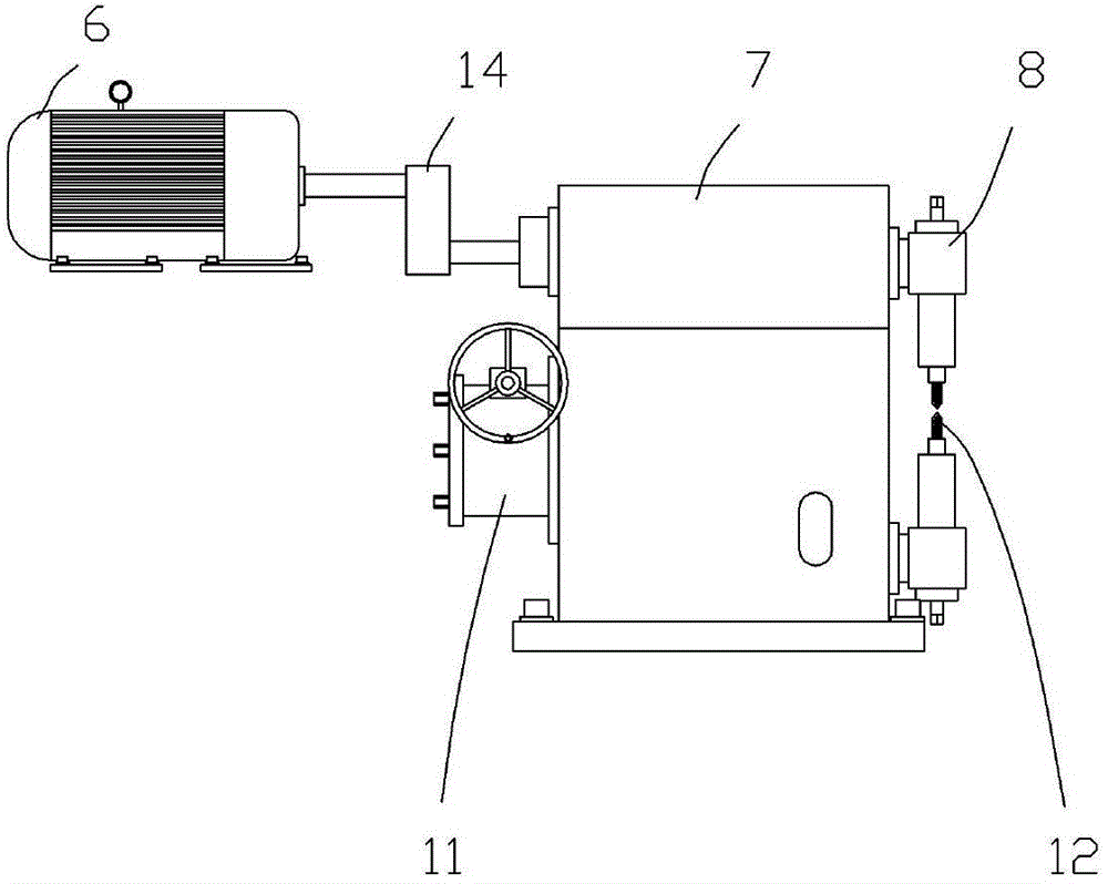
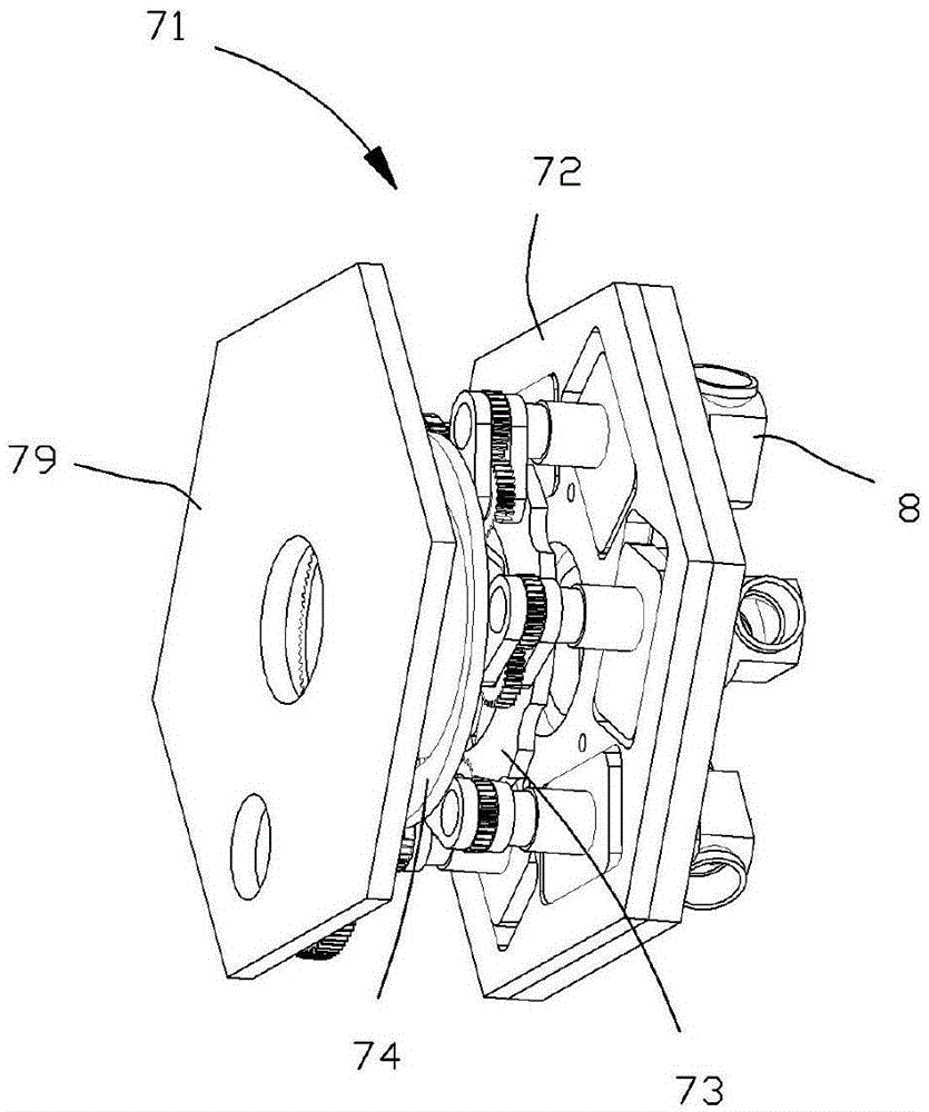
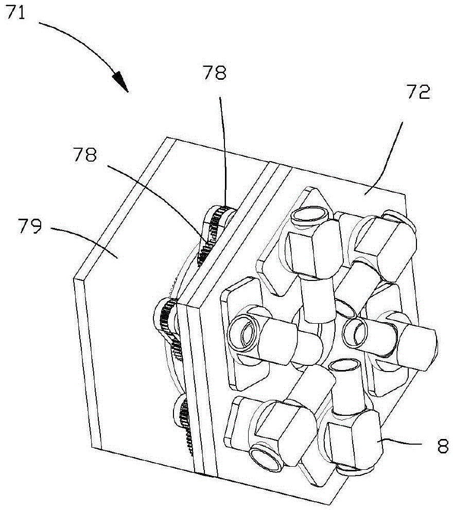
[0033] Such as Figures 1 to 15 Shown is an embodiment of a special-shaped rod chip processing machine head of the present invention, which includes a transmission box 7, a transmission mechanism 71 is arranged in the transmission box 7, and the number of the chip surface of the special-shaped rod is arranged on the transmission box 7. Equal tool mounts 8, a chipping tool 12 that can rotate along the central axis is installed in each tool mounting seat 8, and the chipping tool 12 is distributed in a circular array, and the tip of the chipping tool 12 faces inward, and the chipping tool The rotation center of 12 has an included angle with the center point of the circular array of chip cutters 12 , and the chip cutters 12 are driven to rotate by the transmission mechanism 71 .

[0034] The ...


PUM


Abstract

The invention discloses a machine head for cutting and processing an irregular steel bar. The machine head comprises a transmission case (7), wherein a transmission mechanism (71) is arranged inside the transmission case (7); cutter mounting bases (8), equal with the cutting faces of the irregular steel bar in number, are arranged on the transmission case (7); a cutting tool (12) capable of rotating around a center axis is mounted in each of the cutter mounting bases (8); the cutting tools (12) are distributed in a ring array manner; the tool noses of the cutting tools (12) are towards the inner side; included angles are formed by the rotating centers of the cutting tools (12) and the center points of the ring array of the cutting tools (12); the cutting tools (12) are driven by the transmission mechanism (7) to be rotated. The machine head disclosed by the invention can effectively improve the producing and processing efficiency of the irregular steel bar, and meanwhile reduce the producing and processing cost of the irregular steel bar.

Description

Technical field: [0001] The invention relates to the technical field of special-shaped rod processing equipment, and more specifically relates to a special-shaped rod chip processing machine head. Background technique: [0002] In the prior art, there are mainly two ways to process special-shaped rods (such as hexagonal rods, pentagonal rods, etc.), one of which is to use cold drawing or cold drawing, and the round rods are drawn by cold drawing or cold drawing. Processing into special-shaped rods requires multiple processes, such as removing cracks on the surface of round rods, pickling, annealing, etc., and then passing through a mold by drawing and extrusion molding to obtain special-shaped rods. The method needs to go through multiple processes, the production efficiency is low, and the production cost is relatively high, and the extrusion molding process will inevitably damage the internal crystal phase structure and affect the quality of the rod. Especially this proces...

Claims


Application Information

Patent Timeline
Patent Type & Authority Applications(China)
IPC IPC(8): B23D79/00
Inventor 韩春涛
Owner 泰州浩邦科技发展有限公司
Why Eureka
Try Eureka