Filling pipe for filling of high-viscosity fluid

A high-viscosity, fluid technology, used in liquid distribution, transportation or transfer devices, packaging, distribution devices, etc., to achieve the effect of large operating range, resource saving and accurate measurement

Inactive Publication Date: 2015-06-10
HUBEI XINGRUI SILICON MATERIAL CO LTD
View PDF0 Cites 0 Cited by
  • Summary
  • Abstract
  • Description
  • Claims
  • Application Information

AI Technical Summary

Problems solved by technology

[0003] The technical problem to be solved by the present invention is to provide a crane tube for filling high-viscosity fluids, which can solve the

Method used


Image

  • Filling pipe for filling of high-viscosity fluid
  • Filling pipe for filling of high-viscosity fluid
  • Filling pipe for filling of high-viscosity fluid

Examples


Embodiment Construction

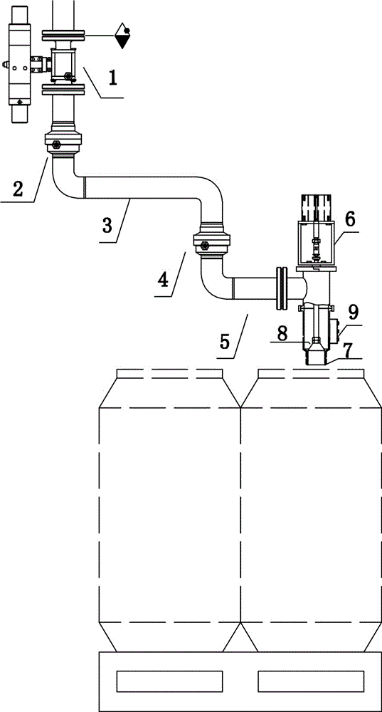
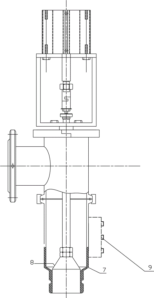
[0019] Such as figure 1 with figure 2 As shown, a crane tube for filling high-viscosity fluids includes a pneumatic ball valve 1, one end of the inner arm 3 is connected to the pneumatic ball valve 1 through the first rotary joint 2, and the other end of the inner arm 3 is connected to the outer tube through the second rotary joint 4. The arm 5 is connected, the end of the outer arm 5 is connected with the spray gun 7 with the pneumatic head 6, and the cover mouth 8 of the spray gun 7 is connected with the pneumatic head 6.

[0020] Pneumatic ball valve 1 is a pneumatic ball valve installed on the feed pipe.

[0021] Spray gun 7 is a large diameter spray gun.

[0022] The caliber of spray gun 7 is Φ89mm.

[0023] Cover mouth 8 is telescopic cover mouth.

[0024] Control box 9 is installed on spray gun 7 sides. The switches of the pneumatic ball valve 1 and the spray gun 7 are controlled by the side-mounted control box 9. Under normal circumstances, the pneumatic head 6 i...


PUM

PropertyMeasurementUnit
Caliberaaaaaaaaaa

Abstract

A filling pipe for filling of high-viscosity fluid comprises a pneumatic ball valve. One end of an inner arm is connected with the pneumatic ball valve through a first rotating joint, and the other end of the inner arm is connected with an outer arm through a second rotating joint; the tail end of the outer arm is connected with a spraying gun with a pneumatic head; and a cover opening of the spraying gun is connected with the pneumatic head. The filling pipe for filling of the high-viscosity fluid can solve the filling problem of existing high-viscosity fluid, is flexible in operation, convenient to use and manufacture, capable of reducing labor intensity of workers, suitable for filling of the high-viscosity fluid, and large in viscosity range, and can be suitable for filling of the fluid, with the viscosity ranging from 10000 MPas to 100000 MPas, such as 107 crude rubber and high-viscosity silicone oil.

Description

technical field [0001] The invention relates to a liquid conveying device, in particular to a crane tube for filling high-viscosity fluid. Background technique [0002] At present, a discharge pipe is generally used for filling high-viscosity fluids, and the filling is controlled manually or automatically by a ball valve. The filling port is fixed, and the barrels need to be placed on the filling line for filling one by one. The position of the barrel is not well placed, the fluid is easy to drip on the filling line, the labor of the workers is cumbersome and it is easy to pollute the workshop environment. Though the crane tube that is made up of steel pipe, rotating device has occurred at present, it is flexible to operate but is mostly used for the loading of low-viscosity substances such as oils, and the crane tube that is applicable to high-viscosity fluid filling has not yet been involved. Contents of the invention [0003] The technical problem to be solved by the p...

Claims


Application Information

Patent Timeline
IPC IPC(8): B67D7/42B67D7/02
Inventor 苗刚胡丹黄潇孙东俊
Owner HUBEI XINGRUI SILICON MATERIAL CO LTD
Why Eureka
Try Eureka