Long-base-line strain gauge and hull beam stress long-term monitoring device

A strain gauge and long baseline technology, applied in the direction of force measurement by measuring the change of magnetic properties of materials caused by applied stress, can solve the problems of difficult to realize real-time monitoring of hull girder stress, complicated calibration process, large temperature drift, etc. Suitable for long-term monitoring, easy to use and accurate measurement

Inactive Publication Date: 2015-06-10
HARBIN ENG UNIV
View PDF7 Cites 4 Cited by
  • Summary
  • Abstract
  • Description
  • Claims
  • Application Information

AI Technical Summary

Problems solved by technology

However, due to the strong randomness of the structural loads of ships navigating in waves, it is impossible to accurately predict these random loads during the design and construction process. Therefore, in order to ensure the safety and expected service life of ship structures during navigation, it is necessary to Long-term real-time monitoring of hull loads and stresses
However, the previous methods often have the defects of being unable to measure the average strain of the hull girder, the calibration process is complicated, the installation is difficult, the temperature drift is large, the accuracy is low, and the cost is high, so it is difficult to realize the real-time monitoring of the hull girder stress.

Method used


Image

  • Long-base-line strain gauge and hull beam stress long-term monitoring device
  • Long-base-line strain gauge and hull beam stress long-term monitoring device
  • Long-base-line strain gauge and hull beam stress long-term monitoring device

Examples


Embodiment example 1

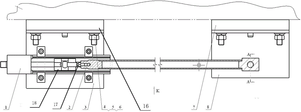
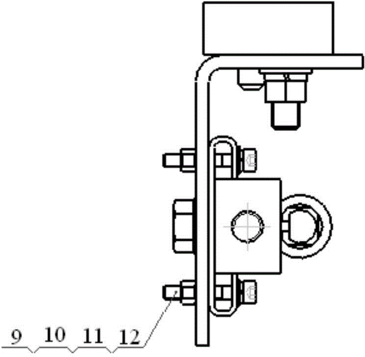
[0012] Implementation case 1: a long baseline strain gauge, including two bases 7 and 16, the first bracket 3 and the second bracket 8 are respectively installed on the two bases 7 and 16, and the magnetostrictive displacement sensor 1 is installed on the first bracket 3 On, one end of the measuring telescopic rod 2 is fixedly connected with one end of the slider installation rod 17 arranged in the middle of the magnetostrictive displacement sensor 1, and the other end of the slider installation rod 17 is connected with the sensor measuring slider 18, and the other end of the measurement telescopic rod 2 One end is fixedly connected with the second bracket.

[0013] When installing the long baseline strain gauge, firstly install the first bracket 3 on the base 16 using the gasket 4, the gasket 5 and the nut 6 respectively, the second bracket 8 adopts the same installation method as the bracket 1, the first bracket 3 and the second bracket 8 The distance between the positioning...

Embodiment example 2

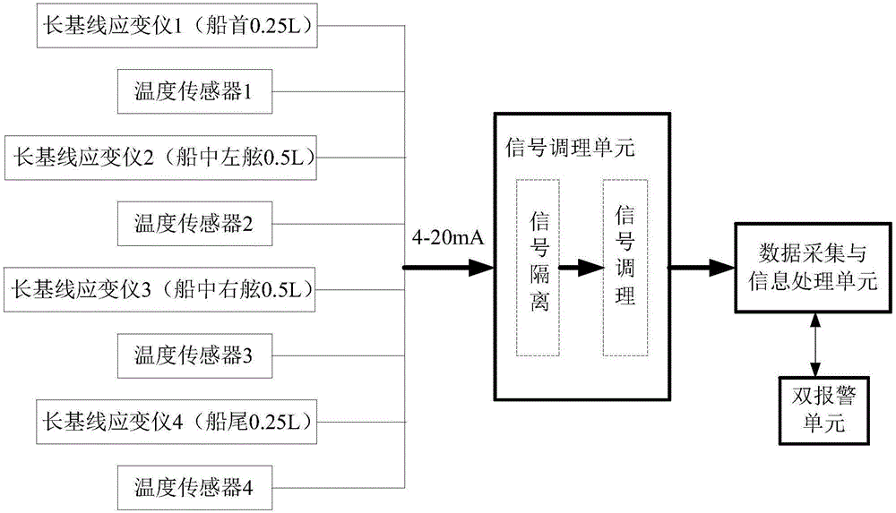
[0015] Implementation case 2: A long-term monitoring device for hull girder stress. A long-baseline strain gauge is fixedly installed on the hull girder, and a temperature sensor is also installed on the hull girder. The signal conditioning unit, the data acquisition and processing computer are connected to the alarm unit; the long baseline strain gauge includes two bases, the first bracket and the second bracket are respectively installed on the two bases, and the magnetostrictive displacement sensor is installed on the first bracket, One end of the measuring telescopic rod is fixedly connected with one end of the slider installation rod arranged in the middle of the magnetostrictive displacement sensor, the other end of the slider installation rod is connected with the sensor measuring slider, and the other end of the measurement telescopic rod is fixedly connected with the second bracket.

[0016] A long-term monitoring device for hull girder stress provided by the present i...


PUM


Abstract

The invention provides a long-base-line strain gauge and hull beam stress long-term monitoring device. The long-base-line strain gauge and hull beam stress long-term monitoring device comprises two bases, wherein a first support and a second support are respectively installed on the two bases, a magnetostrictive displacement sensor is installed on the first support, one end of a measuring extension rod is fixedly connected with one end of a slide block installing rod arranged in the middle of the magnetostrictive displacement sensor, the other end of the slide block installing rod is connected with a sensor measuring slide block, and the other end of the measuring extension rod is fixedly connected with the second support. The long-base-line strain gauge and hull beam stress long-term monitoring device has the advantages of being simple in structure, convenient to install, dispense with calibration, accurate in measurement and free of temperature drift and the like and is suitable for long-term monitoring of hull beam stress and load states of large ships.

Description

technical field [0001] The invention relates to a device for long-term real-time monitoring of hull girder load and stress of a large ship, in particular to a long-baseline strain gauge and a long-term monitoring device for hull girder stress. Background technique [0002] The strength of hull structure is one of the main factors affecting the safety of ship navigation, and the longitudinal strength of hull girder is the most basic and important strength. In order to ensure that the ship girder has sufficient strength to resist the damage of the environmental load to the structure, people have put forward many design ideas and formulated various specifications, processes and maintenance plans in the process of ship design and construction. However, due to the strong randomness of the structural loads of ships navigating in waves, it is impossible to accurately predict these random loads during the design and construction process. Therefore, in order to ensure the safety and ...

Claims


Application Information

Patent Timeline
Patent Type & Authority Applications(China)
IPC IPC(8): G01L1/12
Inventor 曲先强李新飞谢耀国崔洪斌马永亮张猛
Owner HARBIN ENG UNIV
Why Eureka
Try Eureka