Method and device for digitally and automatically controlling bias voltage of electro-optic light modulator

A bias voltage and optical modulator technology, applied in the field of optical processing, can solve problems such as poor stability, high error rate, environmental noise interference, etc., to achieve the effect of ensuring stability, stable working performance, and preventing over-high or under-low

Active Publication Date: 2015-06-10
SHENZHEN PAGE PRECISION SYST
View PDF5 Cites 17 Cited by
  • Summary
  • Abstract
  • Description
  • Claims
  • Application Information

AI Technical Summary

Problems solved by technology

However, the bias control technology is mainly developed based on the analog circuit scheme, which is susceptible to environmental noise interference, poor stability, and high error rate
In addition, the error feedback coefficient of the bias voltage technology in the prior art is fixed, and the half-wave voltage of different types of optical modulator...

Method used


Image

  • Method and device for digitally and automatically controlling bias voltage of electro-optic light modulator
  • Method and device for digitally and automatically controlling bias voltage of electro-optic light modulator
  • Method and device for digitally and automatically controlling bias voltage of electro-optic light modulator

Examples


Embodiment Construction

[0025] The present invention will be described in detail below in conjunction with the accompanying drawings and embodiments.

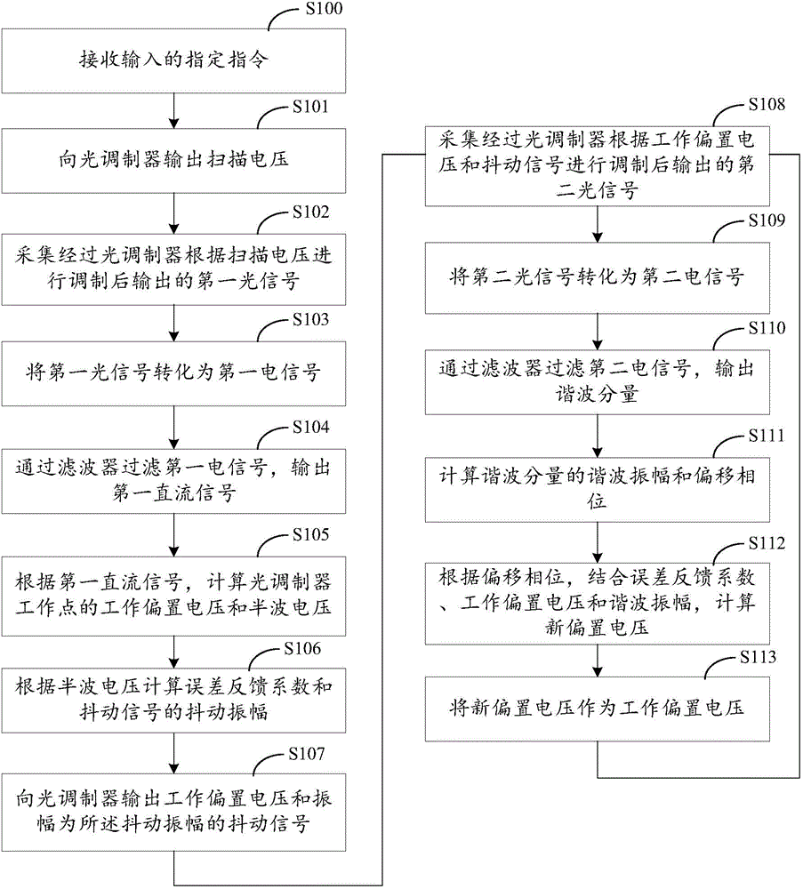
[0026] see figure 1 , the electro-optic optical modulator digital automatic bias voltage control method includes

[0027] Step S101: Outputting a scanning bias voltage to the optical modulator;

[0028] The optical carrier output by the laser and the radio frequency signal output by the radio frequency signal generator are modulated by the optical modulator, and the radio frequency signal is attached to the optical carrier to become an optical signal to realize optical communication.

[0029] Outputting the scanning bias voltage to the light modulator can make the light modulator at a corresponding working point.

[0030] Step S102: collecting the first optical signal output after being modulated by the optical modulator according to the scanning bias voltage;

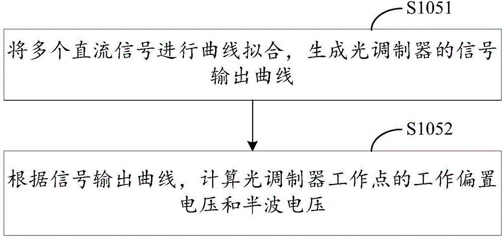
[0031] The optical signal modulated and output by the optical modulator can be collecte...


PUM


Abstract

The invention discloses a method and a device for digitally and automatically controlling bias voltage of an electro-optic light modulator. The method comprises the following steps: after inputting scanning bias voltage to a light modulator, calculating to obtain half-wave voltage of the light modulator; calculating error feedback coefficients and the dithering amplitude of a dithering signal according to the half-wave voltage; after inputting working bias voltage and the dithering signal to the light modulator, calculating to obtain harmonic amplitude and an offset phase; according to the offset phase, combining the error feedback coefficients, the harmonic amplitude and the working bias voltage to calculate to obtain new bias voltage; after taking the new bias voltage as the working bias voltage, returning the step for inputting the working bias voltage to the light modulator. According to the method for digitally automatically controlling the bias voltage of the electro-optic light modulator, in a light modulator working procedure, the working bias voltage can be continuously corrected, so that the working performance of the light modulator is more stable; furthermore, when the new bias voltage exceeds a voltage threshold range, the new bias voltage is modulated back, so that the working bias voltage is prevented from being too high or too low.

Description

technical field [0001] The invention relates to the field of light processing technology, in particular to a digital automatic bias voltage control method and device for an electro-optical light modulator. Background technique [0002] The optical modulator is used to modulate the radio frequency signal and the optical carrier output by the laser to form an optical signal. Among them, the optical modulator is widely used in the fields of optical fiber communication and optical fiber sensing. The output curve of the optical signal modulated by the optical modulator is a waveform in the shape of a cosine function. In order for the light modulator to be controlled at different operating points, a bias voltage can be output to the light modulator. [0003] However, since the optical modulator is extremely sensitive to changes in the working environment, changes in the working environment, such as temperature changes, humidity changes, mechanical vibrations, etc., will cause the...

Claims


Application Information

Patent Timeline
IPC IPC(8): G05F1/46
CPCG05F1/46H04B10/50575G02F1/0115H04B10/25891H04B10/07955H04B10/2575H04B10/516
Inventor 陈宇奇房冰招永湛
Owner SHENZHEN PAGE PRECISION SYST
Why Eureka
Try Eureka