A kind of h-bridge drive circuit and its control method

A bridge drive circuit and drive control circuit technology, applied in the field of power electronics, can solve the problems of large area occupied by capacitors and difficult integration, and achieve the effects of reducing occupied area, reducing energy, and preventing false conduction

Active Publication Date: 2017-07-11
SILERGY SEMICON TECH (HANGZHOU) CO LTD
View PDF3 Cites 0 Cited by
  • Summary
  • Abstract
  • Description
  • Claims
  • Application Information

AI Technical Summary

Problems solved by technology

Although the above prior art requires a simple drive circuit structure, each output requires a C BS Capacitor, and the capacitor occupies a large area, it is difficult to integrate on-chip

Method used


Image

  • A kind of h-bridge drive circuit and its control method
  • A kind of h-bridge drive circuit and its control method
  • A kind of h-bridge drive circuit and its control method

Examples


Embodiment Construction

[0025] Preferred embodiments of the present invention will be described in detail below with reference to the accompanying drawings, but the present invention is not limited to these embodiments. The present invention covers any alternatives, modifications, equivalent methods and schemes made within the spirit and scope of the present invention.

[0026] In order to provide the public with a thorough understanding of the present invention, specific details are set forth in the following preferred embodiments of the present invention, but those skilled in the art can fully understand the present invention without the description of these details.

[0027] In the following paragraphs the invention is described more specifically by way of example with reference to the accompanying drawings. It should be noted that all the drawings are in simplified form and use inaccurate scales, which are only used to facilitate and clearly assist the purpose of illustrating the embodiments of t...


PUM


Abstract

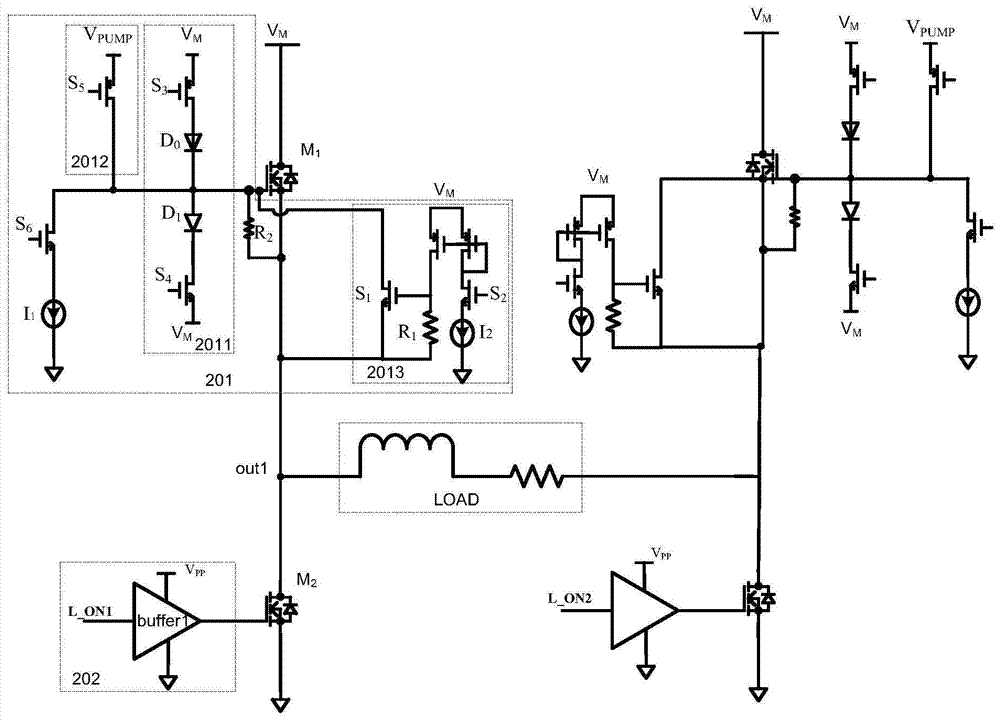
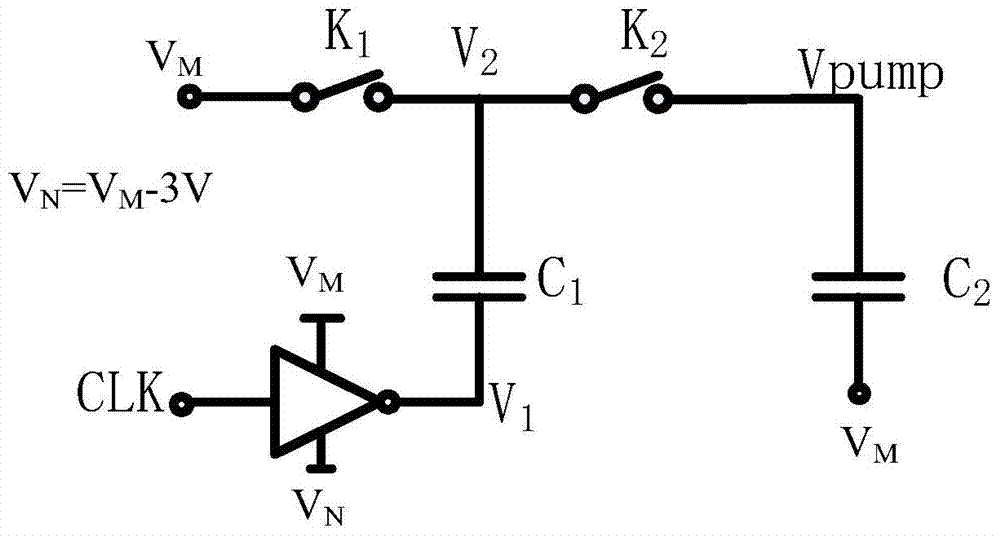
The invention discloses an H-bridge driving circuit and a control method thereof. It adopts pre-charging and discharging, pumps up the input voltage as the driving voltage, realizes the interoperability of the driving voltages output by each channel, and reduces the pull-up time of the pull-up voltage generation circuit. At the same time, the area occupied by the corresponding module is reduced. During pre-discharge, after pre-discharge, the upper power tube enters the Maitreya platform, and the gate is further discharged through the first constant current source. By controlling the size of the first constant current source, The control of the output falling edge can be realized, which solves the problem of excessive EMI caused by too fast falling edge time, and the problem that the input and output delay will be increased if the falling edge is too slow. When both the upper and lower power tubes are turned off, the parasitic diode of the lower tube conducts freewheeling, and the output terminal is negative, which may easily lead to false conduction of the upper transistor. The phenomenon of false conduction can be effectively prevented by clamping the upper transistor.

Description

technical field [0001] The invention relates to the technical field of power electronics, in particular to an H-bridge driving circuit for motor driving and a control method thereof. Background technique [0002] H-bridge (also known as full-bridge) drive circuit is a typical DC motor control circuit. It is composed of two identical circuits through the opening and closing of switches. In each circuit, there are two switching tubes, one of which can be connected to the positive pole. One can be pulled up by one pass, and the other can be pulled down by negative conduction, or vice versa. The two outputs are always kept in opposite directions, so that the polarity of the load can be reversed in the case of a single supply. Because of this connection method and the intermediate load, the drawn shape looks like an H, so it is named H bridge. [0003] Since the on-resistance per unit area of ​​the N-type MOS tube is much smaller than that of the P-type MOS tube, in the drive c...

Claims


Application Information

Patent Timeline
Patent Type & Authority Patents(China)
IPC IPC(8): H02P7/28
Inventor 邱建平
Owner SILERGY SEMICON TECH (HANGZHOU) CO LTD
Why Eureka
Try Eureka