Clamping finger for clamping shaft part

A technology for shaft parts and part clamps, which is applied in the field of clamping fingers for shaft parts, can solve problems such as gaps, parts positioning, and tightness, and achieve the effect of ensuring assembly accuracy

Inactive Publication Date: 2015-06-17
DALIAN UNIV OF TECH
View PDF7 Cites 5 Cited by
  • Summary
  • Abstract
  • Description
  • Claims
  • Application Information

AI Technical Summary

Problems solved by technology

However, due to the manufacturing accuracy of the clamp fingers and the limitation of the shape of the part itself, the end face of the shaft part cannot be tightly a

Method used


Image

  • Clamping finger for clamping shaft part
  • Clamping finger for clamping shaft part

Examples


Embodiment Construction

[0010] The specific implementation manner of the patent of the present invention will be described in detail below in conjunction with the technical scheme and accompanying drawings.

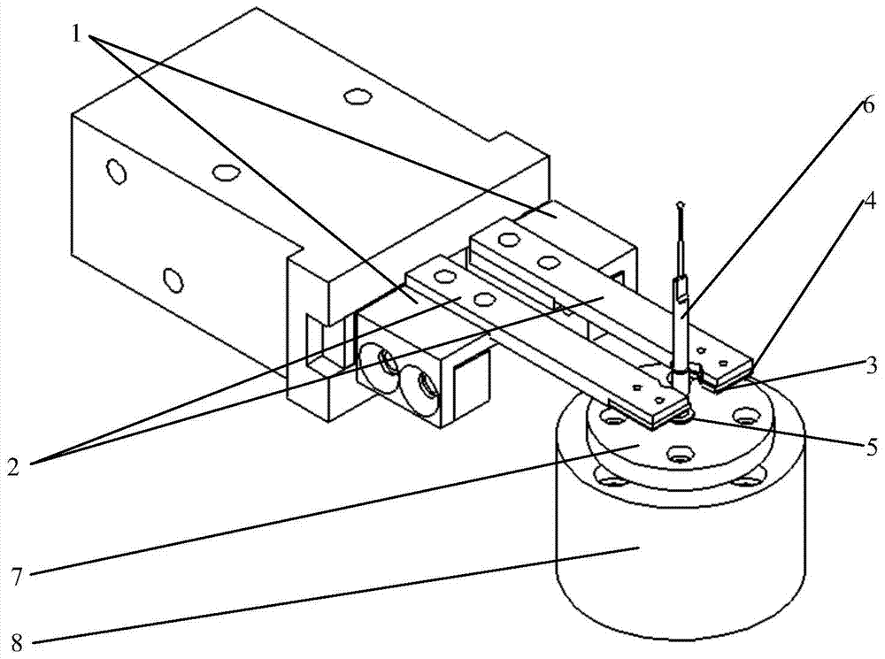
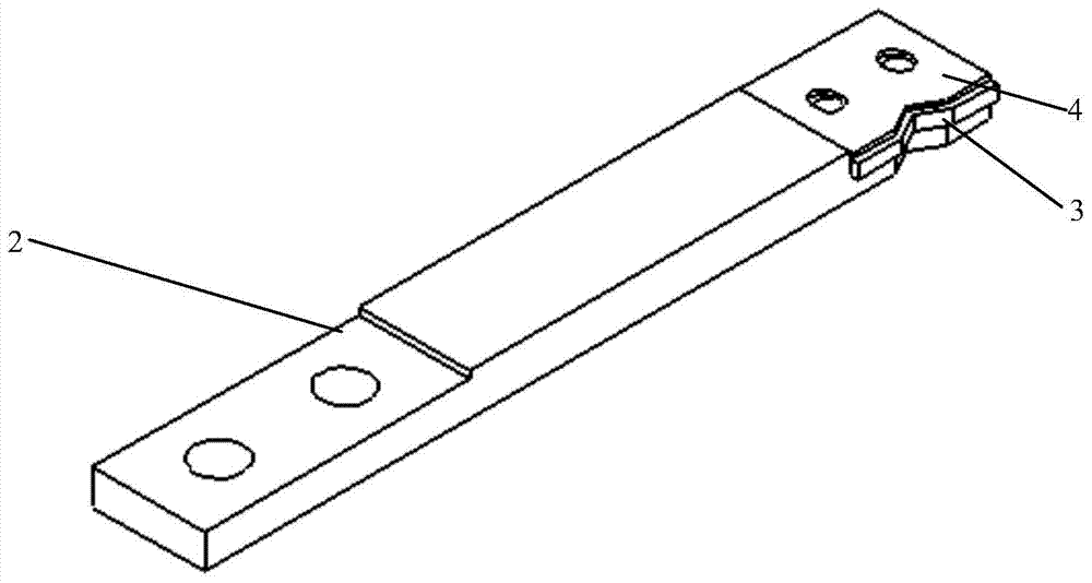
[0011] Such as figure 1 As shown, the opening and closing of the air claw 1 is controlled by the air valve through compressed air. The clamping finger rod 2 is a convex structure. Fix the rubber pad 3 and the sheet 4 in sequence; the V-shaped grooves of the two clamping fingers 2 are opposite to each other for installing the clamped shaft parts 6; V-shaped groove; the rubber pad 3 is wider than the V-shaped groove of the clamp finger bar 2 at the V-shaped groove, and the rubber pad 3 protrudes; the clamped shaft part 6 is fixed on the positioning end face 5, and the positioning end face 5 is located at the center of the positioning disc 7, and the positioning disc 7 is provided with a through hole for fixing with the pressing round table 8; the pressing round table 8 is also provided with a thr...


PUM


Abstract

The invention relates to a clamping finger for clamping a shaft part. The clamped rear end face of the shaft part can be made to be tightly attached to a positioning end face, and it is guaranteed that positioning is reliable. According to the clamping finger, a pneumatic claw is controlled by a pneumatic valve to be opened and closed through compression air, one end a clamping finger rod is fixedly installed on the pneumatic claw through a screw, and a V-shaped groove is machined in the other end of the clamping finger rod; a rubber gasket and a fixed thin sheet are respectively fixed above the V-shaped groove; a V-shaped groove is formed in the rubber gasket in a cutting mode, and when the rubber gasket is fixed to the clamping ringer rod, the rubber gasket is exposed out of the V-shaped groove; when the clamping finger is adopted for clamping the shaft part, because of stressed deformation of the rubber gasket, the fixed thin sheet can be pressed to deform; due to deformation, the shaft part is pushed upwards, the end face of the shaft part is made to be tightly attached to the positioning end face, and the end face positioning purpose is achieved.

Description

technical field [0001] The invention belongs to the field of precision machinery, and relates to a clamping finger for clamping shaft parts, which can make the rear end face of the shaft parts clamped closely to the positioning end face to ensure reliable positioning. Background technique [0002] When clamping shaft parts with fingers, in some cases it is necessary to perform end face positioning, that is, the end face of the shaft part is closely attached to the end face of a certain component. However, due to the manufacturing accuracy of the clamp fingers and the limitation of the shape of the part itself, the end face of the shaft part cannot be tightly attached to the positioning end face after being clamped by the clamp finger, and there will be a gap between the two, which leads to the positioning problem of the part. . Therefore, it is necessary to find a simple and feasible clamping method that can achieve end face positioning and realize reliable clamping and pos...

Claims


Application Information

Patent Timeline
IPC IPC(8): B25B11/02
CPCB25B11/02
Inventor 王晓东娄志峰由博许阳
Owner DALIAN UNIV OF TECH
Why Eureka
Try Eureka