Eureka AIR delivers breakthrough ideas for toughest innovation challenges, trusted by R&D personnel around the world.

Copper cylinder orienting mechanism

A technology of directional mechanism and copper pillars, which is applied in the direction of coating, etc., can solve the problems that the holes on the copper pillars and the mold core cannot be matched circularly and circularly, and the winding cannot be carried out effectively, so as to improve production efficiency, The effect of reducing speed and reducing wear

Inactive Publication Date: 2015-06-17
PIONEDA INTELLIGENT AUTOMATION TECH NINGBO
View PDF5 Cites 0 Cited by
  • Summary
  • Abstract
  • Description
  • Claims
  • Application Information

AI Technical Summary

Problems solved by technology

[0002] In the automatic production process of electric fusion pipe, it is necessary to insert the copper column into the mold core for winding and injection molding. In the winding process, the copper column is first wound and then the same coil is wound on the mold core. The automation of the process and the guarantee of production efficiency, when the winding process is in progress, there is no other positioning device to fix the copper column, which makes it impossible for the copper column and the hole on the mold core to be matched with a circle and a circle, so the circle and the hole The circular fit will cause the copper pillars to rotate during winding, making the winding impossible. Therefore, other shapes need to be used to cooperate with each other, and the mutual fit of other shapes requires the orientation of the copper pillars. At present, there is no Effective way to locate copper pillars

Method used


Image

  • Copper cylinder orienting mechanism
  • Copper cylinder orienting mechanism
  • Copper cylinder orienting mechanism

Examples


Embodiment Construction

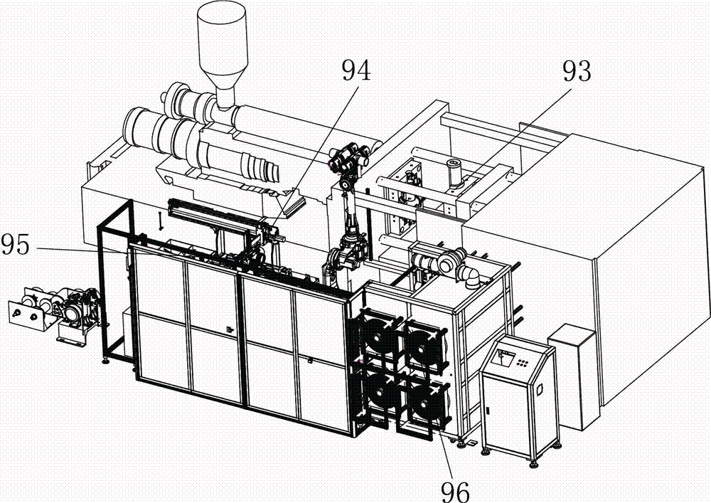
[0029] The present invention will be described in further detail below in conjunction with accompanying drawing and specific embodiment: see figure 1 , automatic production equipment for electrofusion pipes, including copper column feeding mechanism, copper column orientation mechanism, injection mold 93, loading and unloading mechanism 94, electrofusion pipe demoulding structure 95 and cooling system 96.

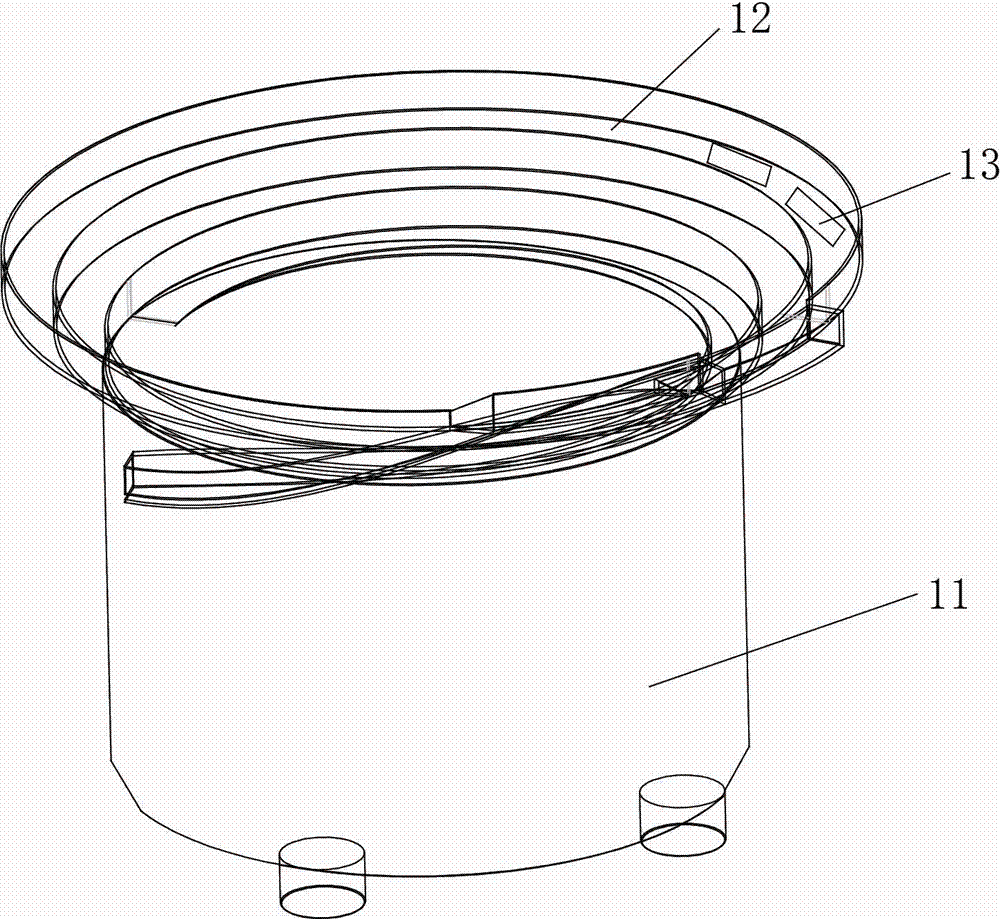
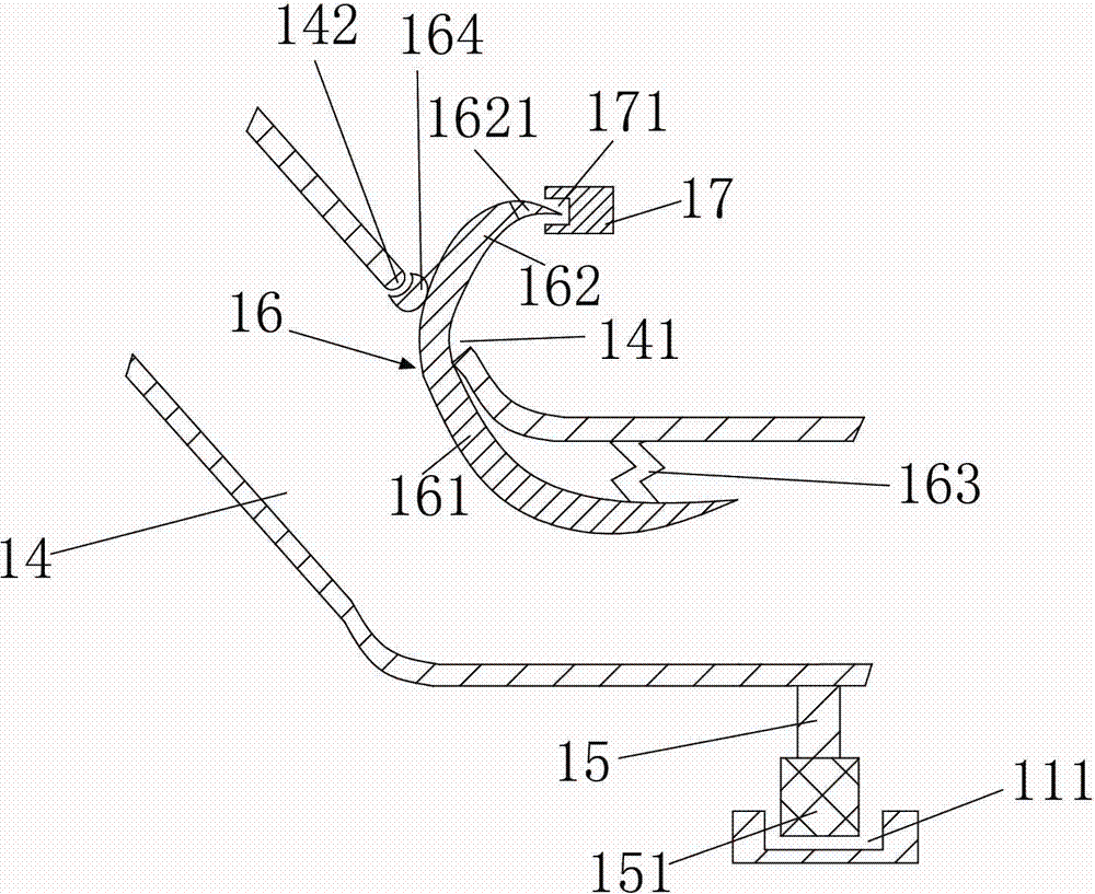
[0030] see Figure 2-4 , the feeding mechanism of the copper column, including a vibrating plate, the vibrating plate includes a vibrating plate body 11 and a track 12, the vibrating plate body 11 holds workpieces, and the track 12 is arranged on the vibrating plate body 11 and is arranged on the vibrating plate body 11 The workpiece is transported, and several gaps 13 are provided on the track 12, and the lower side of the gap 13 is rotatably connected with a blanking channel 14, and a pulley support frame 15 is arranged on the lower side wall of the blanking channel 13, a...


PUM


Abstract

The invention relates to a copper cylinder orienting mechanism; the copper cylinder orienting mechanism comprises a first bracket; a feeding pipeline for transporting a copper cylinder is connected over the first bracket; a first through hole is formed in the first bracket; the feeding pipeline is communicated with the first through hole; a second groove is arranged in the first through hole; an impeller is arranged in the second groove; the impeller is driven by an air blowing device to rotate; an orienting block is arranged below the second groove in the first through hole; and a second through hole matched with the end part of the copper cylinder in shape is arranged on the orienting block. The copper cylinder orienting mechanism disclosed by the invention is capable of automatically orienting the copper cylinder in the transporting process of the copper cylinder; therefore, the copper cylinder is smoothly inserted into the hole of a mould core, so that subsequent production is carried out; and, by means of automatic production, the production efficiency is increased.

Description

technical field [0001] The invention relates to an orientation mechanism for copper pillars. Background technique [0002] In the automatic production process of electric fusion pipe, it is necessary to insert the copper column into the mold core for winding and injection molding. In the winding process, the copper column is first wound and then the same coil is wound on the mold core. The automation of the process and the guarantee of production efficiency, when the winding process is in progress, there is no other positioning device to fix the copper column, which makes it impossible for the copper column and the hole on the mold core to be matched with a circle and a circle, so the circle and the hole The circular fit will cause the copper pillars to rotate during winding, making the winding impossible. Therefore, other shapes need to be used to cooperate with each other, and the mutual fit of other shapes requires the orientation of the copper pillars. At present, there ...

Claims


Application Information

Patent Timeline
Patent Type & Authority Applications(China)
IPC IPC(8): B29C45/14B29C33/12B29C45/17
Inventor 方敏明畅明辉
Owner PIONEDA INTELLIGENT AUTOMATION TECH NINGBO
Why Eureka
Eureka Blog
Learn More