
Cotton cleaning machine

A cotton cleaning machine and cotton machine technology, applied in the field of cotton cleaning machines, can solve the problems of inability to blow raw materials, affecting the efficiency of impurity removal, and inability to remove impurities and clean up.

Active Publication Date: 2018-05-11
NINGBO HIGH TECH ZONE SHENGWENTU TEXTILE CO LTD
View PDF8 Cites 8 Cited by
  • Summary
  • Abstract
  • Description
  • Claims
  • Application Information

AI Technical Summary

Problems solved by technology

When removing impurities in the cotton cleaning process, the airflow cleaning and impurity removal method is often used, such as the domestic airflow directly conveying the impurity removal type and the latest foreign airflow 180-degree swing type impurity removal device; but the following technical problems exist in the prior art: 1. When the airflow is used to remove impurities, the impurities cannot be removed and cleaned; 2. After the raw materials are blown away, the raw materials cannot be concentrated and then blown again, which affects the efficiency of impurity removal.

Method used


Image

  • Cotton cleaning machine
  • Cotton cleaning machine
  • Cotton cleaning machine

Examples


Embodiment Construction

[0024] The present invention will be described in further detail below by means of specific embodiments:

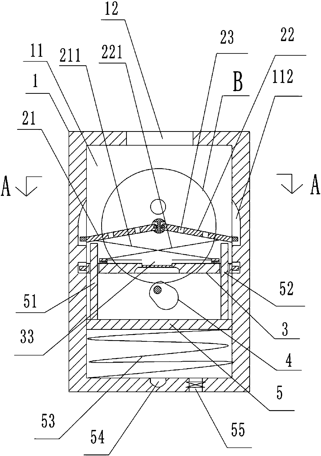
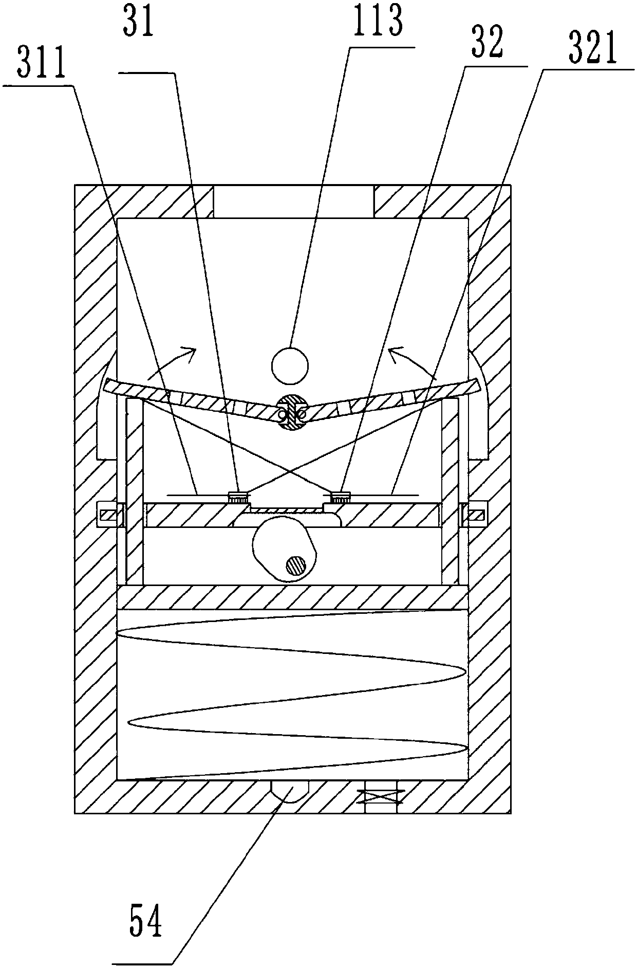
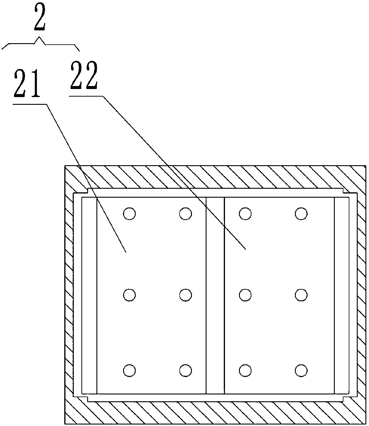
[0025] The reference signs in the accompanying drawings of the specification include: cotton cleaning machine body 1, cleaning chamber 11, rotating shaft 111, rotating groove 1111, rotating shaft 1112, arc groove 112, air blowing port 113, material inlet 12, miscellaneous filter plate 2, The first folding plate 21, the first pull wire 211, the second folding plate 22, the second pull wire 221, the filter hole 23, the cleaning plate 3, the first cleaning brush 31, the first chute 311, the second cleaning brush 32, the second Chute 321, cleaning channel 33, discharge pipe 34, groove 35, cam 4, piston 5, first push rod 51, second push rod 52, return spring 53, air blowing pipe 54, air intake pipe 55.

[0026] Such as figure 1 , figure 2 , image 3 and Figure 4 Shown, in order to achieve the above object, basic scheme of the present invention is as follows:

[0027] A ...


PUM


Abstract

The invention relates to the technical field of spinning, in particular to a cotton cleaning machine. The cotton cleaning machine includes a cotton cleaning machine body, and a cleaning cavity and a feeding inlet are formed in the cotton cleaning machine body. The cleaning cavity is internally provided with an impurity filtering plate, a cleaning plate, a cam and a piston from top to bottom; the cam is connected with a motor, the inner wall of the cleaning cavity is fixedly provided with a rotating shaft, the impurity filtering plate includes a first folding plate and a second folding plate rotatably connected with the two sides of the rotating shaft, and the connection portion of the first folding plate and the rotating shaft and the connection portion of the second folding plate and therotating shaft are provided with torsional springs, and the first folding plate and the second folding plate are provided with filtering holes; a first cleaning brush, a second cleaning brush and a cleaning channel are arranged / formed on / in the cleaning plate; the upper surface of the piston is fixedly provided with a first push rod and a second push rod; a reset spring is arranged between the piston and the bottom surface of the cleaning cavity; the bottom surface of the cleaning cavity is provided with an air inlet pipe and an air blow pipe, and the upper portion of the rotating shaft is provided with a air-blowing port communicated with the air blow pipe. According to the scheme, after scattered materials are gathered, the materials can be scattered again through blowing, and impurities can be cleaned away and discharged.

Description

technical field [0001] The invention relates to the technical field of spinning, in particular to a cotton cleaning machine. Background technique [0002] The spinning process is generally: 1. Cleaning process; 2. Carding machine; 3. Combing process; 4. Drawing process; 5. Roving process; 6. Spinning process. [0003] Cotton cleaning is to grab the raw materials from the cotton bale according to the selected ratio, mix them evenly, open them into small cotton blocks or small cotton bundles, remove some impurities and defects, and then integrate a cotton layer with a certain width, thickness or weight. Wind into a cotton roll. When removing impurities in the cotton cleaning process, the airflow cleaning and impurity removal method is often used, such as the domestic airflow directly conveying the impurity removal type and the latest foreign airflow 180-degree swing type impurity removal device; but the following technical problems exist in the prior art: 1. When the airflow...

Claims


Application Information

Patent Timeline
Patent Type & Authority Applications(China)
IPC IPC(8): D01G9/00D01G9/14D01G9/20
CPCD01G9/00D01G9/14D01G9/20
Inventor 孙文清
Owner NINGBO HIGH TECH ZONE SHENGWENTU TEXTILE CO LTD
Learn More