Vehicle anti-collision system and vehicle anti-collision method

An anti-collision system and vehicle technology, applied to vehicle components, input parameters of external conditions, control devices, etc., can solve problems such as complex control methods, high costs, and collisions.

Active Publication Date: 2015-06-17
AUTOMOTIVE RES & TESTING CENT
View PDF3 Cites 13 Cited by
  • Summary
  • Abstract
  • Description
  • Claims
  • Application Information

AI Technical Summary

Problems solved by technology

[0002] When the driver sits inside the car, due to the limited view angle of the human eye, it is impossible to take into account all directions at the same time, especially when parking and reversing, often because the driver does not pay attention or the sight cannot be taken into account at the same time, it is easy to have a collision. Therefore, how to prevent vehicle collisions is one of the main research goals of manufacturers
[0003] The early vehicle collision avoidance technology is passive safety warning. When the vehicle is too close to an obstacle, it will generate a warning to remind the driver to pay attention. At present, it has evolved into active automatic emergency braking, and most of them use hydraulic brake control system or electronic stability system ( Electronic Stability Program, abbreviated as ESP, also known as electronic body stabilization system) is used with a distance sensor. However, whether it is a hydraulic brake control system or an electronic stability system, both have problems of high cost and complicated control methods

Method used


Image

  • Vehicle anti-collision system and vehicle anti-collision method
  • Vehicle anti-collision system and vehicle anti-collision method
  • Vehicle anti-collision system and vehicle anti-collision method

Examples


Embodiment Construction

[0065] The present invention will be described in detail below in conjunction with the accompanying drawings and embodiments.

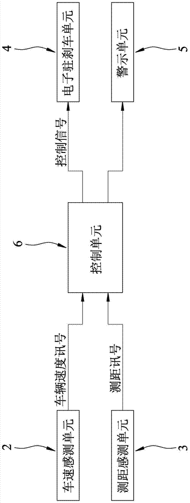
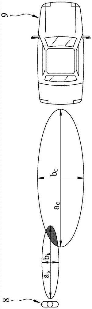
[0066] refer to figure 1 and figure 2 , the preferred embodiment of the vehicle anti-collision system of the present invention is suitable for being arranged on a vehicle 9, and the vehicle anti-collision system comprises: a vehicle speed sensing unit 2, a distance measuring sensing unit 3, an electronic parking brake unit 4 (Electronic Parking Brake , abbreviated as EPB), a warning unit 5, and a control unit 6.

[0067] The vehicle speed sensing unit 2 is used for sensing the speed of the vehicle 9 and outputting a corresponding vehicle speed signal.

[0068] The ranging sensing unit 3 is used to sense the relative distance between the obstacle 8 around the vehicle 9 and the vehicle 9 and output a corresponding ranging signal. The ranging sensing unit 3 can use radar (Radar) or lidar (LightDetectionAndRanging, abbreviated as LiDAR, also known as ...


PUM


Abstract

A vehicle anti-collision system comprises a vehicle speed sensing unit, a distance measuring sensing unit, an electronic parking brake unit and a control unit. The vehicle speed sensing unit is used for sensing the speed of a vehicle; the distance measuring sensing unit is used for sensing the relevant distance from an obstacle around the vehicle to the vehicle; the control unit is used for calculating a period of time in which the vehicle will collide with the obstacle according to the speed of the vehicle, and the relevant distance from the obstacle to the vehicle, and controlling the electronic parking brake unit to provide brake assistance for the vehicle when the collision duration is not longer than a period of brake time. The electronic parking brake unit is arranged and matched with the vehicle speed sensing unit and the distance measuring sensing unit, brake assistance can be executed to avoid the vehicle collision situation at the condition of low-speed reversing or parking, and the arrangement cost of the system can be reduced.

Description

technical field [0001] The invention relates to an anti-collision system and method, in particular to a vehicle anti-collision system and method. Background technique [0002] When the driver sits inside the car, due to the limited view angle of the human eye, it is impossible to take into account all directions at the same time, especially when parking and reversing, often because the driver does not pay attention or the sight cannot be taken into account at the same time, it is easy to have a collision. Therefore, how to prevent vehicle collisions is one of the main research goals of manufacturers. [0003] The early vehicle collision avoidance technology is passive safety warning. When the vehicle is too close to an obstacle, it will generate a warning to remind the driver to pay attention. At present, it has evolved into active automatic emergency braking, and most of them use hydraulic brake control system or electronic stability system ( Electronic Stability Program, ...

Claims


Application Information

Patent Timeline
Patent Type & Authority Applications(China)
IPC IPC(8): B60W30/08B60W30/09B60W40/105B60W40/02
CPCB60W30/08B60W30/09B60W40/02B60W40/105B60W2554/00
Inventor 姚启骏陈俊傑黄世杰李明鸿
Owner AUTOMOTIVE RES & TESTING CENT
Why Eureka
Try Eureka