NC automation right-angle track

A right-angle, track technology, applied in the direction of conveyor objects, conveyors, mechanical conveyors, etc., can solve problems such as precise transportation, restrictions on automated transportation or processing accuracy, and increased track space requirements

Inactive Publication Date: 2015-06-17
UNIV OF SHANGHAI FOR SCI & TECH
View PDF6 Cites 8 Cited by
  • Summary
  • Abstract
  • Description
  • Claims
  • Application Information

AI Technical Summary

Problems solved by technology

In the current large-scale automated production, most of the automatic transportation or processing is realized through the reciprocating motion of the moving parts on the linear track. Due to the limitation of the space position of the linear track, the moving parts cannot be transported more accurately, let alone complete The quarter-turn movement required by the space limits the accuracy of automated transportation or processing to a certain extent
[0003] Although the cross-shaped track in the prior art solves the above problems to a certain extent, the moving parts cannot move independently on the X-axis or Y-axis track, that is, if the moving part moves on the track in the X-axis direction, it will simultaneously Drive the guide rail of the Y axis to move
Makes the space requirement of the track bigger, and if the robot arm is installed on the moving part, the space will increase again

Method used


Image

  • NC automation right-angle track
  • NC automation right-angle track
  • NC automation right-angle track

Examples


Embodiment 1

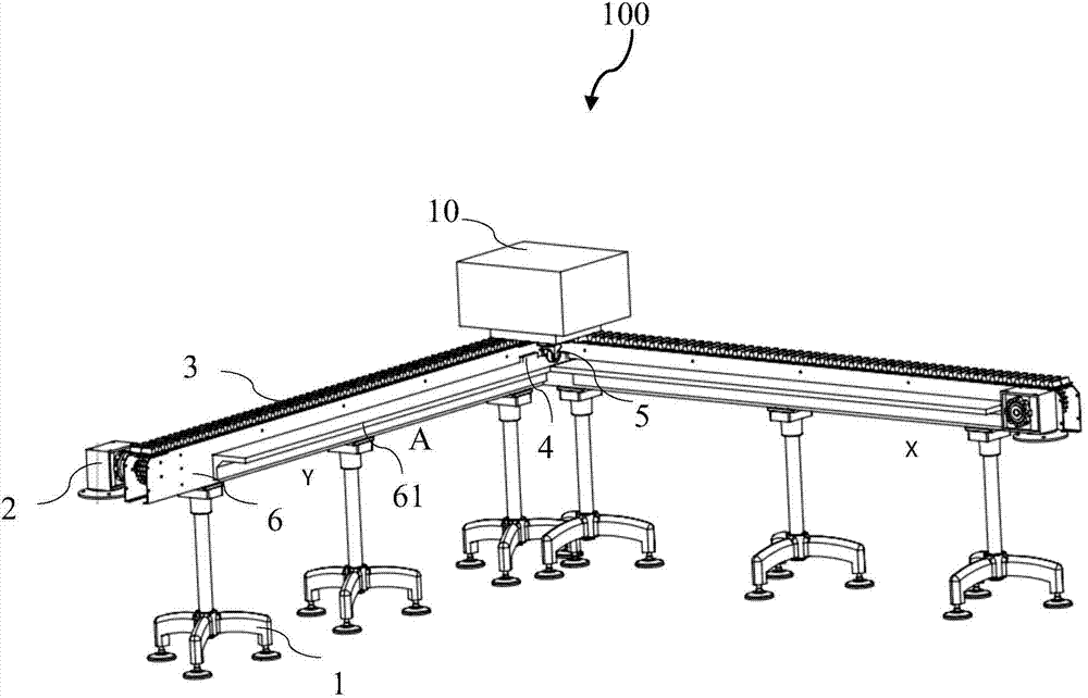
[0023] figure 1 It is a structural schematic diagram of the NC automation right-angle track in this embodiment.

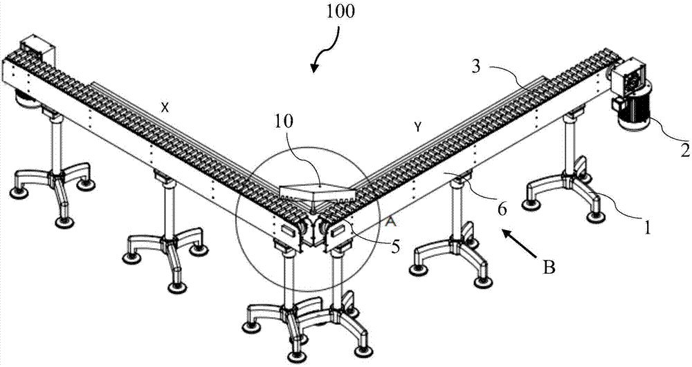
[0024] figure 2 for figure 1 Rear view of the right-angle track for NC automation in .

[0025] like figure 1 and figure 2 As shown, the NC automation right-angle track 100 is composed of two parts with the same structure and forming a right angle. Among the two parts, one is arranged along the X-axis, which is called the X-axis track, and correspondingly, the other part is called the Y-axis track. The specific structure of the NC automated right-angle track is described in detail below.

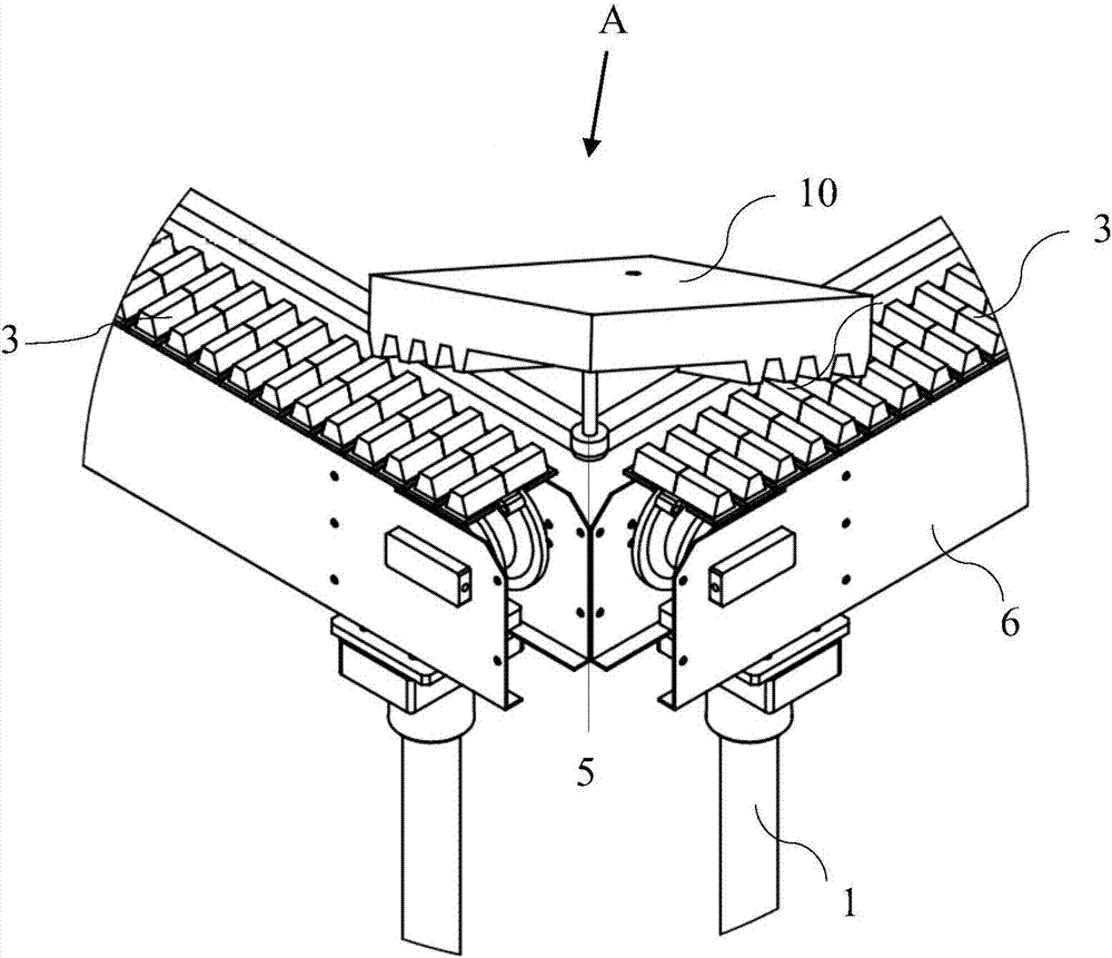
[0026] The NC automated right-angle track 100 includes a supporting part 1 , a driving part 2 , a transmission part 3 , an induction part 4 , a universal wheel device 5 and sheet metal shells 6 arranged on both sides of the transmission part 3 . The support part 1 includes an X-direction support part and a Y-direction support part forming a right angle; the drive part 2 i...

Embodiment 2

[0040] In the second embodiment, the same structures as in the first embodiment are given the same symbols, and the same descriptions are omitted.

[0041] Figure 7 It is a structural schematic diagram of the NC automation right-angle track in this embodiment.

[0042] like Figure 7 As shown, the difference between the NC automated right-angle track 200 and the NC automated right-angle track 100 in Embodiment 1 lies in the drive part 7, which consists of a slide rail 71 close to the drive part 2 and a tooth shape close to the right-angle intersection. Band 72 composed.

[0043] The structure of the bottom end of the moving part 20 is also improved accordingly, that is, the outer ends on the left and right sides are chute 201 matched with the slide rail, and the structure of the inner bottom end of the chute is the same as that of the moving part 10 in the first embodiment.

[0044] When the moving part 20 starts to move from the end of one track to the end of the track on...


PUM


Abstract

The invention provides an NC automation right-angle track. The NC automation right-angle track comprises a supporting part, a driving part, a transmission part and an induction part, wherein the supporting part is composed of an X-direction supporting part and a Y-direction supporting part which form a right angle, the driving part and the transmission part are located at ports of the X-direction supporting part and the Y-direction supporting part, and the induction part is used for detecting the position of a motion component. In the NC automation right-angle track, the part, located at the right-angle intersection, of the transmission part is provided with tooth-shaped belts which form a right angle and are arranged along the X axis and the Y axis, and meshing teeth matched with the tooth-shaped belts are arranged at the bottom end of the motion component; the Y-axis meshing teeth and the Y-axis tooth-shaped belt of the motion component are exactly meshed while the X-axis meshing teeth and the X-axis tooth-shaped belt of the motion component are separated under control of the motion component, and therefore steering of the motion component is completed. By means of the NC automation right-angle track, independent and split movement of the motion component on an X-axis track or a Y-axis track can be achieved, and the space requirement of the track is further lowered.

Description

technical field [0001] The invention belongs to the field of NC automation tracks, in particular to an NC automation right-angle track. Background technique [0002] With the development and improvement of science and technology, the production scale is developing in the direction of large-scale, and the automatic conveying cycle system to complete the material conveying task is indispensable in the production line. In the current large-scale automated production, most of the automatic transportation or processing is realized through the reciprocating motion of the moving parts on the linear track. Due to the limitation of the space position of the linear track, the moving parts cannot be transported more accurately, let alone complete The quarter-turn movement required by space limits the accuracy of automated transport or processing to a certain extent. [0003] Although the cross-shaped track in the prior art solves the above problems to a certain extent, the moving part...

Claims


Application Information

Patent Timeline
Patent Type & Authority Applications(China)
IPC IPC(8): B65G35/06B65G47/52
Inventor 杨雷白国振杨培培汪仕阳梅强辛静王巧然
Owner UNIV OF SHANGHAI FOR SCI & TECH
Why Eureka
Try Eureka