Kiln waste heat system for automatically controlling amount of hot water input into heat exchanger

一种热交换器、窑炉的技术,应用在炉子控制装置、炉、废热处理等方向,达到加强传热、避免低温腐蚀的效果

Inactive Publication Date: 2015-06-17
SHANDONG UNIV OF TECH
View PDF3 Cites 0 Cited by
  • Summary
  • Abstract
  • Description
  • Claims
  • Application Information

AI Technical Summary

Problems solved by technology

However, how to ensure the maximum utilization and avoid low-temperature corrosion in the relevant waste heat utilization system, these problems need to be solved urgently

Method used


Image

  • Kiln waste heat system for automatically controlling amount of hot water input into heat exchanger
  • Kiln waste heat system for automatically controlling amount of hot water input into heat exchanger
  • Kiln waste heat system for automatically controlling amount of hot water input into heat exchanger

Examples


Embodiment Construction

[0042] The specific embodiments of the present invention will be described in detail below in conjunction with the accompanying drawings.

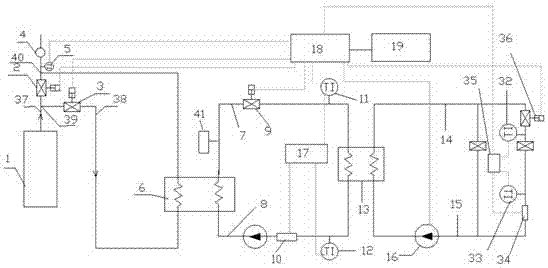
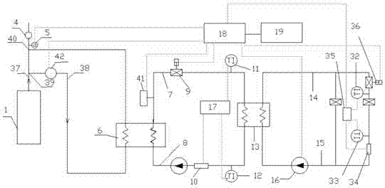
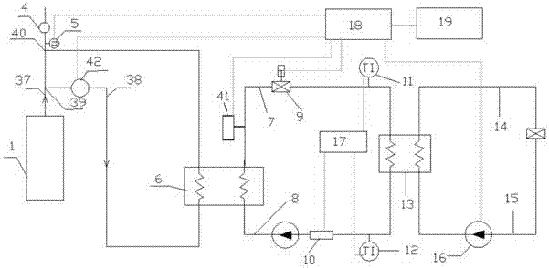
[0043] Such as Figure 1-2 As shown, a cogeneration system of heat and power includes a waste heat system, a heat exchange system and a heat dissipation system, wherein the heat exchange relationship between the waste heat system and the heat exchange system is carried out through an air-water heat exchanger 6, and the heat exchange system and the heat dissipation system are passed through A heat exchanger 13 is connected for heat exchange.

[0044] figure 1 A kiln waste heat utilization system is shown, the system includes a kiln 1, a main flue 37, a bypass flue 38 and an air-water heat exchanger 6, and the flue gas generated by the kiln passes through the bypass flue inlet 39 After entering the air-water heat exchanger 6, the flue gas after heat exchange flows into the main flue 37 through the outlet 40 of the bypass flue and then is d...


PUM


Abstract

The invention provides a kiln waste heat utilization system. The kiln waste heat utilization system comprises a kiln, a main flue, a bypass flue and a gas-water heat exchanger, wherein a first adjustment valve is arranged on a hot water supply pipe in order to adjust hot water entering the heat exchanger; a second adjustment valve is arranged on a water inlet pipeline of a heat user radiator, a programmable logic controller is in data connection with the first adjustment valve and the second adjustment valve, when the opening degree of the second adjustment valve changes, the opening degree of the first adjustment valve correspondingly changes, and therefore the hot water input into the heat exchanger correspondingly changes. The kiln waste heat utilization system can automatically control the hot water input into the heat exchanger according to the opening degrees of the adjustment valves of the radiator, and enables the heat exchange efficiency of the heat exchanger to be maximized, thereby achieving the purposes of being environmentally friendly and saving energy.

Description

technical field [0001] The invention belongs to the field of waste heat utilization and belongs to the field of F27 kilns. . Background technique [0002] With the rapid development of my country's economy, energy consumption is increasing day by day, and the problem of deteriorating urban air quality is becoming more and more prominent. It is urgent to save energy and reduce the emission of harmful environmental substances. In the common thermal power field, one of the main reasons for high energy consumption and serious pollution is that the exhaust gas temperature of the flue gas is too high, which wastes a lot of energy and causes environmental pollution. The cement industry is a high energy consumption and high pollution industry. The tail gas produced by cement rotary kiln has high dust concentration and poor quality. The waste heat utilization system for cement rotary kiln can recover and reuse the waste heat of tail gas to achieve the purpose of energy saving and ...

Claims


Application Information

Patent Timeline
Patent Type & Authority Applications(China)
IPC IPC(8): F27D17/00F27D19/00
CPCY02P10/25
Inventor 孙福振
Owner SHANDONG UNIV OF TECH
Why Eureka
Try Eureka