Rigidity change device and method applicable to vortex-induced vibration testing system

A test system, vortex-induced vibration technology, used in fluid dynamics tests, measuring devices, testing of machine/structural components, etc. There are quite a lot of problems, such as consuming a lot of time, to achieve the effect of simple and convenient pre-balancing work, reducing test costs and test cycles, and reducing workload

Active Publication Date: 2015-06-17
TIANJIN UNIV
View PDF4 Cites 6 Cited by
  • Summary
  • Abstract
  • Description
  • Claims
  • Application Information

AI Technical Summary

Problems solved by technology

However, there are two important technical problems in this method: (1) the transformation of the system stiffness, (2) the vibrator pre-balancing method after the stiffness transformation
However, there are many problems in VCK: (1) the use of sensors, main control system, servo motor and transmission will inevitably increase the test cost; (2) too many sensors will inevitably change the physical characteristics of the test model (mass, flow around (3) VCK is not intuitive, and the test process relies too much on the sensor and the main control system. Once a problem occurs, it is difficult to detect it. Even if the problem is found, it will take a lot of time to solve it, which will increase the test cycle.
However, the vertical arrangement of the vibrator is generally only suitable for the drag test of the static tank; for the vortex induced vibration test in the flowing tank, the difference in flow velocity between the top and bottom of the tank, the influence of the bottom boundary and the free liquid surface, and the influence of the two ends of the vibrator The asymmetry of the arrangement necessarily leads to considerable bias in the test results

Method used


Image

  • Rigidity change device and method applicable to vortex-induced vibration testing system
  • Rigidity change device and method applicable to vortex-induced vibration testing system
  • Rigidity change device and method applicable to vortex-induced vibration testing system

Examples


Embodiment Construction

[0041] The present invention will be described in further detail below in conjunction with the accompanying drawings.

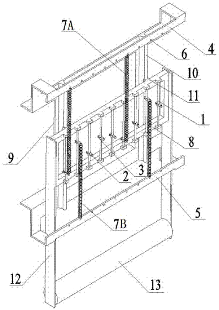
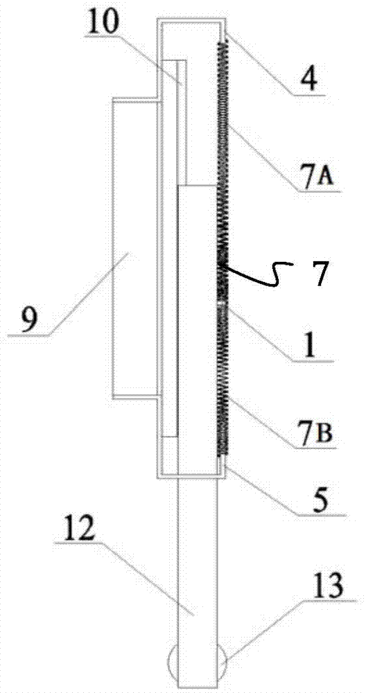
[0042] attached by figure 1 And attached figure 2 It can be seen that the present invention includes a hanging track 1, a hook 2, a buckle 3, an upper hanging beam 4, a lower hanging beam 5, a hanging hole 6, a tension spring 7, a sliding frame 8, a bearing frame 9, and a sliding track 10 . The hanging rail 1 and the hook 2 are made of stainless steel, and the upper hanging beam 4 and the lower hanging beam 5 are made of steel; One correspondence; the hanging track 1 is arranged on the sliding frame 8 at intervals, and the hook 2 is moved and fixed on the hanging track 1 through the buckle 3; the upper hanging beam 4 and the lower hanging beam 5 are respectively fixed on the bearing Above and below the frame 9, the hanging holes 6 are arranged on the upper hanging beam 4 and the lower hanging beam 5 at intervals according to corresponding positions, stric...


PUM


Abstract

The invention discloses a rigidity change device and method applicable to a vortex-induced vibration testing system, and relates to the field of ocean dynamic and fluid and solid coupling testing. A physical spring is used for simulating system rigidity, defects in application of VCK are avoided, a linear overlapping principle is used, flexible changes of the spring on a hanging point of a sliding system is realized, and the work of system rigidity changes and work of vibrator pre-balance are made to be simpler and more convenient. Meanwhile, the aspects of selection of numbers and specializations and hanging of springs are more flexible, the testing cost is greatly reduced, the testing period is greatly shortened, and the testing efficiency is increased.

Description

technical field [0001] The invention relates to the field of marine dynamics and fluid-solid coupling tests, and relates to a physical device and a corresponding stiffness change method suitable for stiffness changes of a vortex-induced vibration test system. Background technique [0002] At a specific flow rate, the back side of the blunt body with a relatively large slenderness will generate alternating shedding vortices, and the pressure difference caused by the elasticity of the blunt body itself and the vortex shedding will make the blunt body follow the frequency (or multiplier) of vortex shedding. On the other hand, because the periodic motion of the blunt body changes the characteristics of the flow field, the vortex shedding behavior of the fluid changes, and this change causes the change of the motion of the structure again; finally, the fluid and the blunt body The body has reached a balance under mutual interference and action, and they are all in a stable state ...

Claims


Application Information

Patent Timeline
Patent Type & Authority Applications(China)
IPC IPC(8): G01M10/00
Inventor 燕翔张军任泉超刘昉
Owner TIANJIN UNIV
Why Eureka
Try Eureka