
Method for effectively correcting main magnetic field of magnetic resonance imaging system

A magnetic resonance imaging and main magnetic field technology, which is applied in the direction of measuring magnetic variables, measuring devices, instruments, etc., can solve time-consuming and high-complexity problems

Inactive Publication Date: 2015-06-17
ZHEJIANG UNIV
View PDF3 Cites 5 Cited by
  • Summary
  • Abstract
  • Description
  • Claims
  • Application Information

AI Technical Summary

Problems solved by technology

Passive shimming itself has a high complexity because the number of sampling points in the shimming film and imaging space reaches as many as hundreds, and it is a pathological problem.
Under the action of the main magnetic field, the shimming sheet is magnetized to generate a magnetic field for shimming, and at the same time, it will also generate eddy current effects, which will affect the result of shimming
In the practice of MRI passive shimming, in order to find an acceptable result, the shimming process usually has to be repeated many times, which makes shimming a very time-consuming task in the MRI engineering process

Method used


Image

  • Method for effectively correcting main magnetic field of magnetic resonance imaging system
  • Method for effectively correcting main magnetic field of magnetic resonance imaging system
  • Method for effectively correcting main magnetic field of magnetic resonance imaging system

Examples


Embodiment Construction

[0040] The present invention will be described in detail below with specific examples in conjunction with the accompanying drawings.

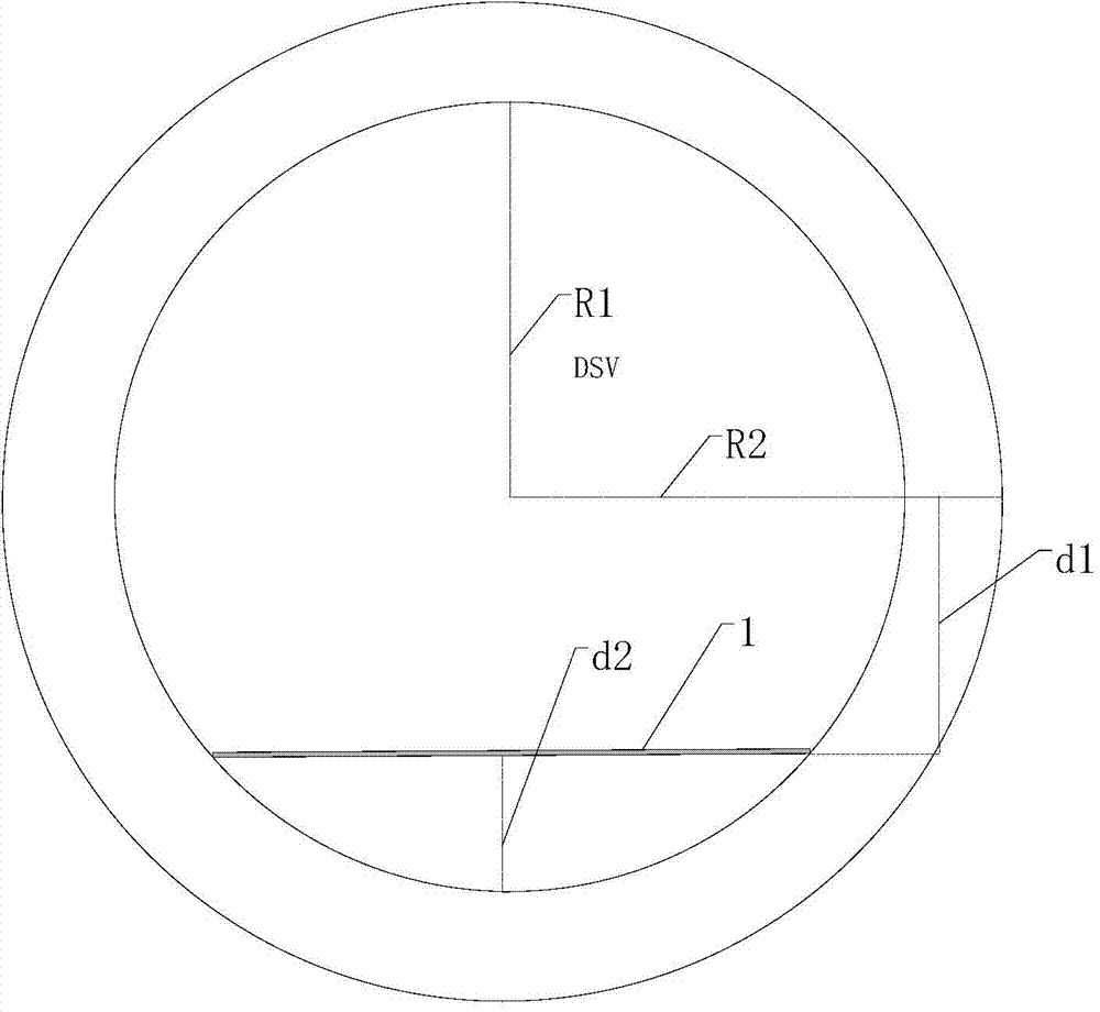
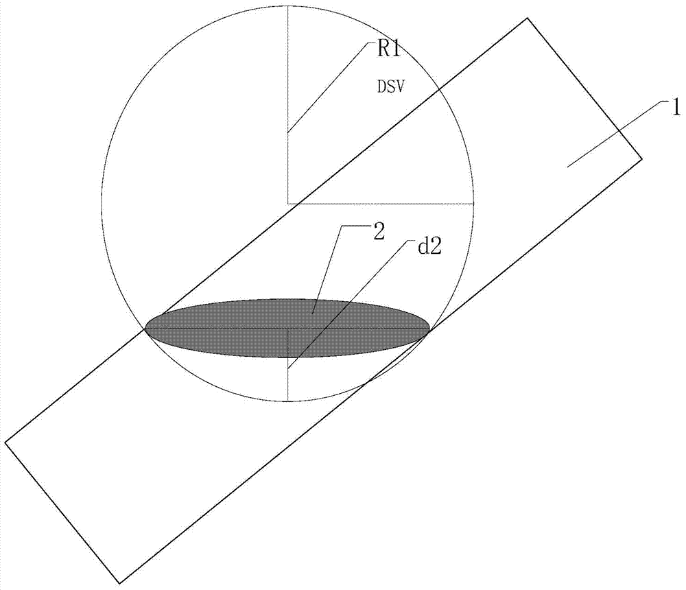
[0041] During the scanning process of the MRI system, the patient lies on the hospital bed that is designed to be closer to the ground (the inner wall of the bottom magnet), which leaves more space above the patient to reduce the patient's MRI scan. claustrophobic. During the process of the patient's MRI scan, the patient bed is controlled by the computer so that the parts to be detected of the human body, such as the head, torso and limbs, are pushed into the DSV center of the system. However, due to the existence of the hospital bed, the DSV will be divided into two parts, making the space below the hospital bed (including the hospital bed) out of the imaging space, which will not be involved in imaging but the standard shimming process will still Consider a portion of the spatial region. In the theoretical design stage of a superconducting...


PUM


Abstract

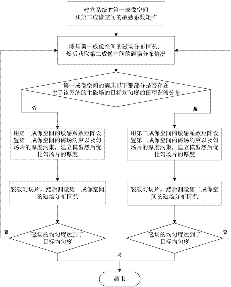
The invention discloses a method for effectively correcting a main magnetic field of a magnetic resonance imaging system. During a scanning process of the magnetic resonance imaging system, imaging space of the magnetic resonance imaging system is divided into two parts by a sickbed, one is the part above the sickbed, involved in the imaging scanning process, of the imaging space, and the other one is the part under the sickbed, separated from the imaging scanning, of the imaging space. When harmonic components shaped like a Chinese character 'tian' which are larger than the target uniformity of the main magnetic field of the system exist in the part, under the sickbed, of the imaging space of the magnetic resonance imaging system, shimming can be only conducted on the part above the sickbed, involved in the imaging scanning process, of the imaging space; shimming is conducted on the whole imaging space of the magnetic resonance imaging system otherwise. According to the method for effectively correcting the main magnetic field of the magnetic resonance imaging system, a standard shimming hardware system is not changed, and the method for effectively correcting the main magnetic field of the magnetic resonance imaging system is applicable to the vast majority of the magnetic resonance imaging systems for human body imaging.

Description

technical field [0001] The invention relates to a method for effectively correcting the main magnetic field of a magnetic resonance imaging system. Background technique [0002] The main magnetic field of the imaging space (also called diameter of the special volume, DSV) of the magnetic resonance imaging (Magnetic Resonance Imaging, MRI) system needs to meet the requirement of near perfect uniformity (a change of a few millionths, parts per million (ppm, 10 -6 ,millionth)). The generation of a highly uniform and strong magnetic field in the imaging space of the magnetic resonance imaging system often requires the use of superconducting (superconducting, SC) technology. A theoretical superconducting magnet design can provide an ideal high-quality magnetic field environment in the imaging space of an MRI system. However, in the manufacturing process of MRI superconducting magnets, some unavoidable production errors will cause the inhomogeneity of the magnetic field (usuall...

Claims


Application Information

Patent Timeline
IPC IPC(8): G01R33/565
Inventor 夏灵孔霞刘锋
Owner ZHEJIANG UNIV
Learn More