Card locking structure for card holder connector

A technology for connectors and locking cards, which is applied in the field of card locking structure for card socket connectors, can solve the problems of poor precision, position can only be far away from the card slot, and short length, etc., and achieves simple molding, facilitates guided insertion, and improves strength Effect

Inactive Publication Date: 2015-06-17
SUZHOU HANMAI ELECTRONICS
View PDF5 Cites 2 Cited by
  • Summary
  • Abstract
  • Description
  • Claims
  • Application Information

AI Technical Summary

Problems solved by technology

However, if Figure 7 As shown, the traditional locking structure and plastic integrated injection molding are usually relatively fragile due to the influence of space and injection molding manufacturing process, and the ordinary locking structure is affected by space and injection molding manufacturing process, and the position can only be far away from the card slot, and the length is relatively long. Short, there is a problem of poor guiding accuracy

Method used


Image

  • Card locking structure for card holder connector
  • Card locking structure for card holder connector
  • Card locking structure for card holder connector

Examples


Embodiment Construction

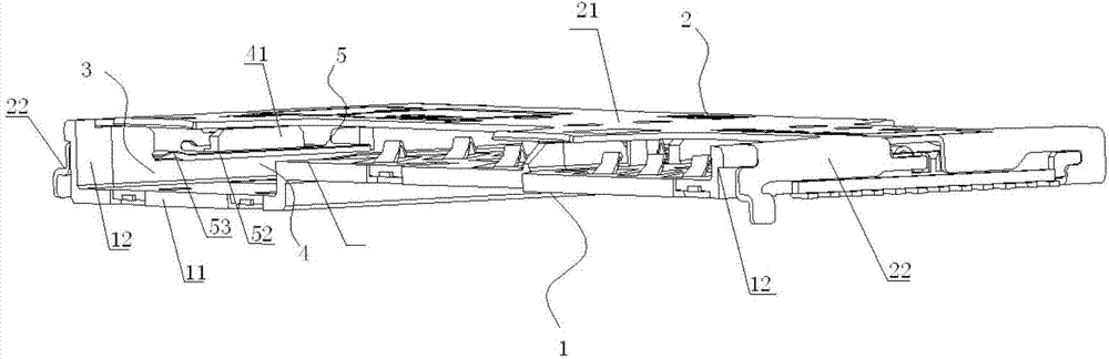
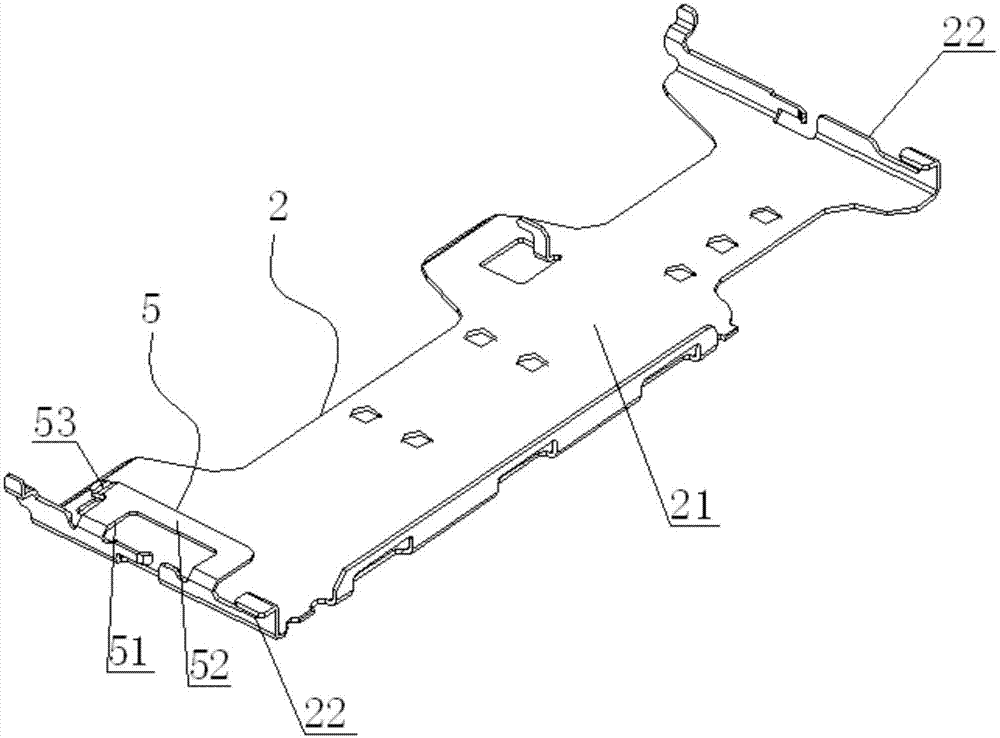
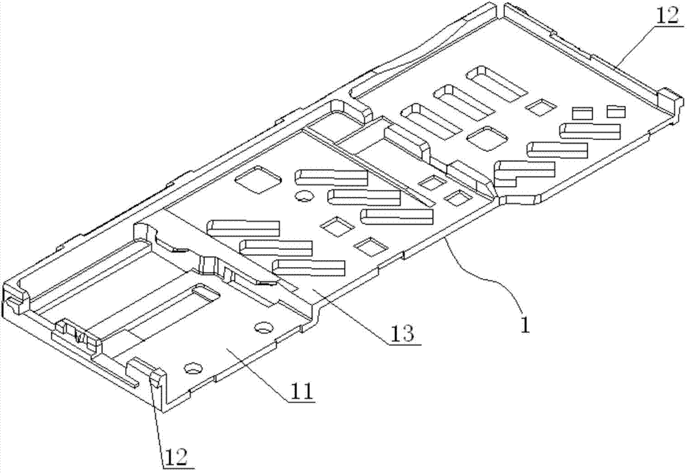
[0033] Such as figure 1 , figure 2 , image 3 , Figure 4 , Figure 5 and Figure 6 As shown, a locking structure for card socket connectors includes an insulating bottom case 1 and a metal upper cover 2, the insulating bottom case includes a bottom case body 11 and a side wall 12 of the bottom case, and the metal upper cover includes an upper cover body 21. Both sides of the upper cover body are respectively bent and extended to form an upper cover side wall 22, the upper cover side wall of the metal upper cover and the bottom shell side wall of the insulating bottom shell are buckled together, A folded card slot 4 with a card insertion slot 3 is formed, wherein a side wall of the upper cover is bent and extended toward the middle of the folded card slot and passes through the side wall of the upper cover to form at least one guide spacer 5, so that The guide spacer divides the folded card slot into at least two card slots 41 for inserting the card 6 . In the above st...


PUM


Abstract

The invention discloses a card locking structure for a card holder connector. The card locking structure for the card holder connector comprises an insulating bottom shell and a metal upper cover, wherein the insulating bottom shell comprises a bottom shell body and bottom shell side walls, the metal upper cover comprises an upper cover body, each of the two sides of the upper cover body is bent and extends to form an upper cover side wall, the upper cover side walls of the metal upper cover are combined with the bottom shell side walls of the insulating bottom shell to form an overlapped clamping groove with a card insertion opening, one upper cover side wall is bent and extends towards the middle of the overlapped clamping groove and penetrates through the upper cover side wall to form at least one guiding partition piece, and the overlapped clamping groove is divided into at least two card insertion grooves allowing cards to be inserted therein by the guiding partition piece. According to the card locking structure for the card holder connector, the approximate card insertion opening design can be achieved, a card is guided once the card is inserted, and thus the ideal requirement for blind insertion can be achieved; compared with a traditional card locking structure, the strength of the card locking structure can be greatly improved.

Description

technical field [0001] The invention relates to a card holder connector for a mobile phone, in particular to a card locking structure for the card holder connector. Background technique [0002] At present, a plurality of SIM card connectors and memory card connectors are arranged in a mobile phone or a mobile phone, and the SIM card connector is used to insert a SIM card applied to a mobile phone to realize the electrical connection between the SIM card and the circuit board inside the mobile phone; The connector is used to insert the memory card (TF card) used in the mobile phone to realize the electrical connection between the memory card and the circuit board inside the mobile phone. With the development of miniaturization and ultra-thinning of mobile phones, traditional separate SIM card connectors and memory card connectors usually need to occupy a larger or thicker space on the motherboard, which makes it difficult to arrange other devices on the motherboard, which li...

Claims


Application Information

Patent Timeline
Patent Type & Authority Applications(China)
IPC IPC(8): H01R13/631H01R13/639H01R12/71H01R13/46H01R27/02H04M1/02
Inventor 李怀恒
Owner SUZHOU HANMAI ELECTRONICS
Why Eureka
Try Eureka