Method and system for identifying cable termination plugs and ports on a computer

A computer system, computer technology, applied in computer parts, computing, transmission systems, etc., can solve problems such as difficult installation and interconnection

Active Publication Date: 2017-08-29
IBM CORP
View PDF1 Cites 0 Cited by
  • Summary
  • Abstract
  • Description
  • Claims
  • Application Information

AI Technical Summary

Problems solved by technology
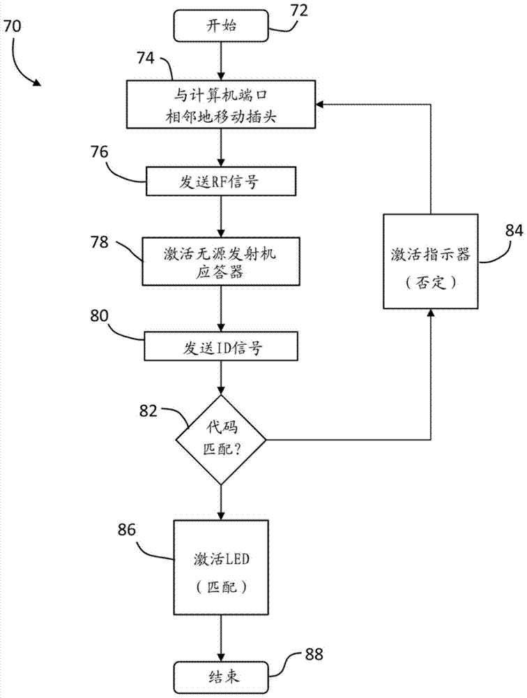
However, these interconnects are often difficult to mount using a backplane template or cables into which the interconnect circuit board plugs in using backplane connectors

Method used


Image

  • Method and system for identifying cable termination plugs and ports on a computer
  • Method and system for identifying cable termination plugs and ports on a computer
  • Method and system for identifying cable termination plugs and ports on a computer

Examples


Embodiment Construction

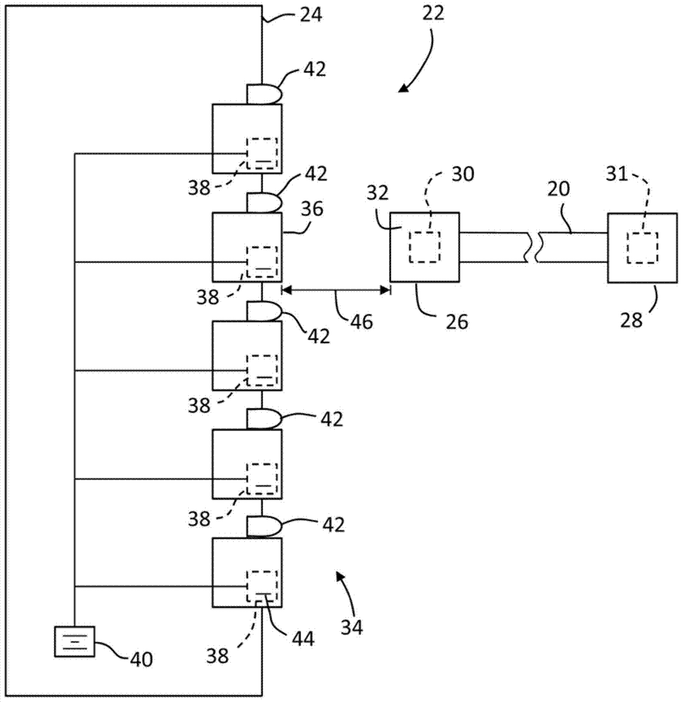
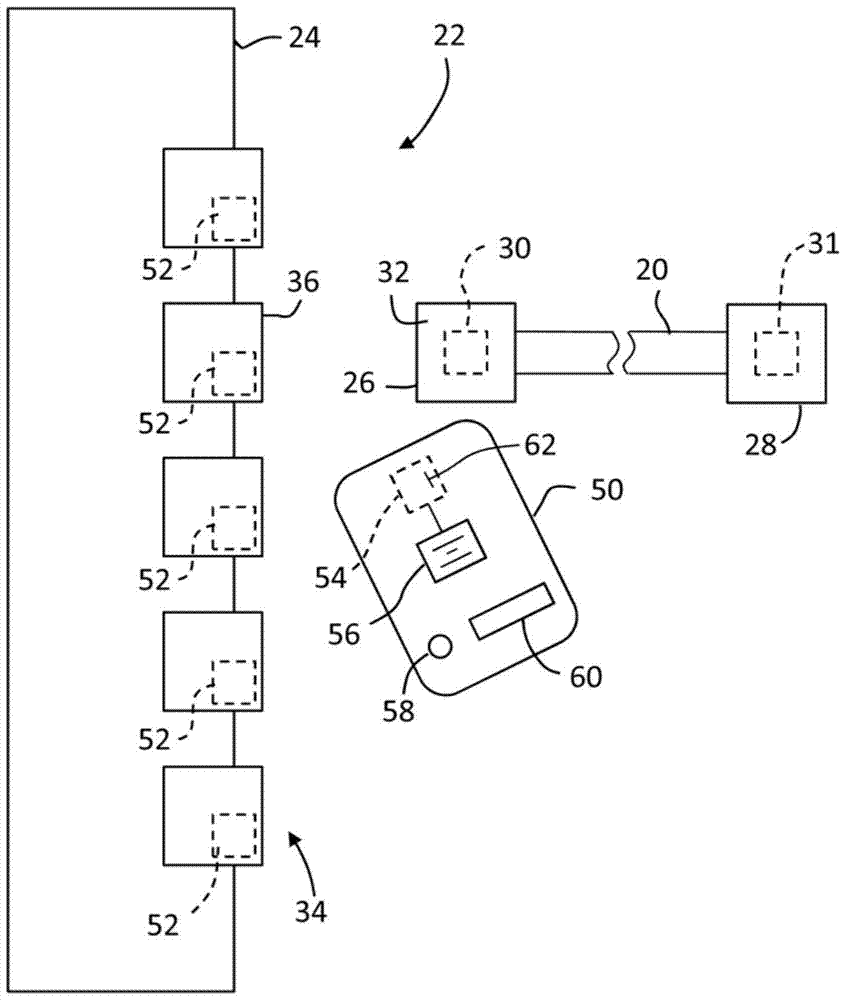
[0009] Embodiments of the present disclosure may be employed in conjunction with interconnected networks of computers, switches, and other information technology devices, such as high-density networks of large cluster systems, high performance computing and supercomputing systems, and cloud computing systems. Embodiments of the present disclosure may be applied to electrical or optical backplanes, cable arrays, connector arrays, and wires for interconnecting tens or hundreds of switching elements called switches or switching ICs or switching chips. cable harness.

[0010] Combining many switching elements (on the order of 16 to 64 or 128 switching elements in some embodiments) each having links to most or all of the other switching elements in one or more stages Embodiments of the present disclosure are used with so-called "all-to-all" or "full mesh" networks. Such a network with ports interconnecting each switching element or with a large number of other switching elements (...


PUM


Abstract

Embodiments relate to systems and methods for identifying cable termination plugs and ports on a computer system. One aspect includes a method having the step of positioning a cable plug adjacent a computer port, the cable plug having a passive transponder. Sends RF signals to passive transponders. Passive transponders are activated with an RF signal. An identification signal is transmitted based on the received RF signal. Make sure the identification signal matches the identification value of the computer port.

Description

technical field [0001] The present invention relates generally to systems for tracking cables, and more particularly, the present invention relates to systems for mating cable termination plugs with server ports. Background technique [0002] Modern high performance computer systems often involve interconnections between printed circuit boards or between the various servers comprising the system. These types of interconnects are capable of high performance and high density - supporting hundreds and in some cases as many as thousands of interconnect lines operating at rates possibly in excess of 1-10 Gbps. However, these interconnections are often difficult to mount using a backplane template or cables into which the interconnecting circuit board is plugged using backplane connectors. The result is the use of cable connectors (or backplane type connectors) and bulk cables with wires or flex circuitry. It should be appreciated that a large computing system or supercomputer m...

Claims


Application Information

Patent Timeline
Patent Type & Authority Patents(China)
IPC IPC(8): H01R43/26H01R13/66H01R13/717H01R13/641G02B6/38
CPCH04L41/24H04L41/12G06K7/10158
Inventor C.M.德库萨蒂斯A.拉奥
Owner IBM CORP
Why Eureka
Try Eureka