

Portable power source with clip
A mobile power supply and clip technology, which is applied in the direction of current collectors, electric vehicles, electrical components, etc., can solve the problems of inconvenient placement, and achieve the effects of saving placement space, convenient pick and place, and preventing forgetting
- Summary
- Abstract
- Description
- Claims
- Application Information
AI Technical Summary
Problems solved by technology
Method used
Image

Examples
Embodiment Construction
[0015] The present invention is described in further detail now in conjunction with accompanying drawing. These drawings are all simplified schematic diagrams, which only illustrate the basic structure of the present invention in a schematic manner, so they only show the configurations related to the present invention.
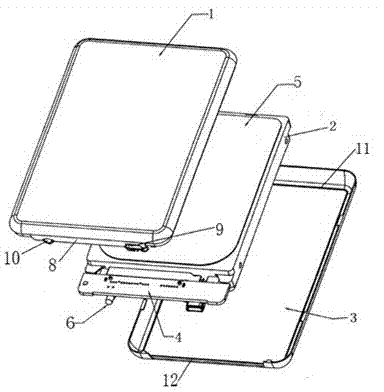
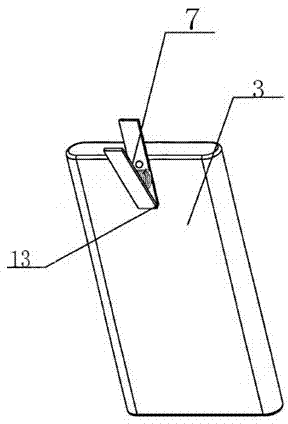
[0016] like figure 1 and figure 2 As shown, a mobile power supply with a clip includes a face shell, a middle frame and a bottom shell, and the middle frame includes an LED display lamp, a USB module, an electric energy storage module and a PCB circuit board, and the LED display lamp and the USB module It is fixedly arranged on the PCB circuit board, and the PCB circuit board is fixed on the electric energy storage module through screws and screw holes; a clip with a clamping mouth is also provided on the bottom case.
[0017] The clip is arranged on the outer side of the bottom case; the end of the bottom case that matches the PCB circuit board is ...
PUM
 Abstract
Description
Claims
Application Information