

Electromagnetic motor
A technology for electromagnetic motors and axial motors, applied to synchronous motors with stationary armatures and rotating magnets, conductive materials for windings, shape/style/structure of winding conductors, etc., can solve problems of poor consistency and low production efficiency High, high working voltage and other problems, to achieve the effect of miniaturization, saving man-hours, and realization of circuit design
- Summary
- Abstract
- Description
- Claims
- Application Information
AI Technical Summary
Problems solved by technology
Method used
Image

Examples
Embodiment 1
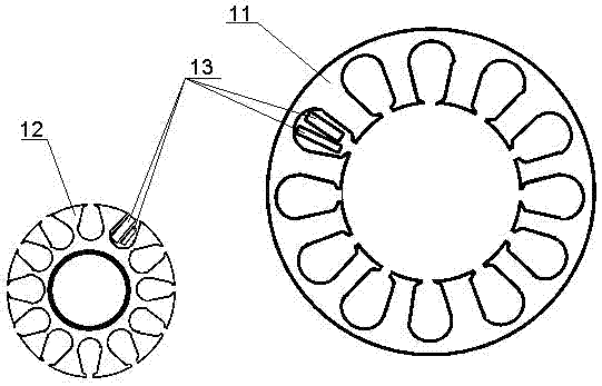
[0030] An embodiment of the electromagnetic motor according to the present invention can refer to Figure 5 and Figure 6 , is a disc motor, including a stator 101 and a mover 102, the stator and the mover have a hollow structure, and the mover is sleeved outside the stator. The specific structure is that the stator 101 is a hollow positioning sleeve, which is fixed on the substrate 104 (in this embodiment, the PCB or FPC on which the stator winding is printed), and at least one pair of mover poles 1022 are installed on the bottom of the mover. At least two stator windings are printed on the substrate (e.g. using figure 2 or image 3 Winding shown) 1013. The mover is set outside the positioning sleeve and can rotate around the positioning sleeve; the mover can be a pure iron core, in this case, the magnetic poles 1022 of the mover can be simply embedded in the iron core; the mover can also be made of Made of non-magnetic material such as plastic, the magnetic pole 1022 of...
Embodiment 2
[0033] According to another embodiment of the electromagnetic motor of the present invention can refer to Figure 7 and Figure 8 , is a disk motor, including a stator 201 and a mover 202. Compared with Embodiment 1, the main difference is that the mover has a mover winding 2023 used as an excitation winding. The specific structure includes that the rotor sleeve 2021 of the mover is set inside the stator sleeve 2011, two stator electrodes (conductive rings) 2014 are arranged on the stator base plate 204, and two mover electrodes (conductive spring pieces) 2024 are arranged on the The mover substrate (in this embodiment, the PCB or FPC on which the mover winding 2023 is printed) 205 is respectively used to maintain electrical connection with the two conductive rings during the rotation. This enables the stator 201 to supply power to the mover winding through the conductive ring and the conductive spring sheet.
[0034] In this embodiment, the end face of the mover is in conta...
Embodiment 3
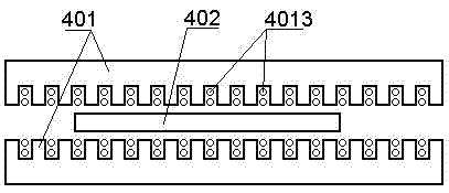
[0038] According to another embodiment of the electromagnetic motor of the present invention can refer to Figure 9 and Figure 10 , is a compound motor based on an axial motor, including a stator 301 and a mover 302 (the stator and mover poles of the axial motor are not shown in the figure) and the winding 303 of the axial motor realized by PCB or FPC, It is also provided with magnetic poles and windings of a disc motor on one end face of the stator and / or the mover.
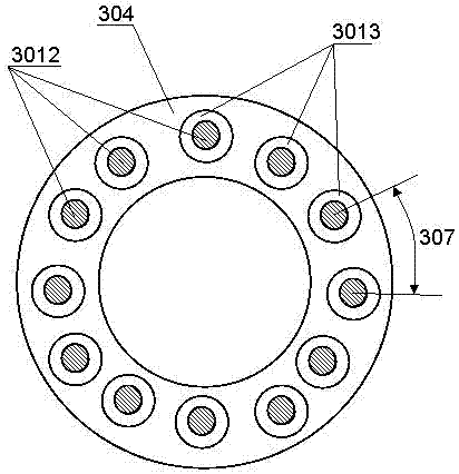
[0039] The magnetic poles and windings of the disk motor include the stator poles and windings (if any) of the disk motor and the mover poles and windings (if any) of the disk motor. refer to Figure 10 , The stator pole 3012 of the disc motor can be made by an integrated method on the end face of the stator, or it can be installed separately. The mover magnetic poles of the disc motor can be integrated with the mover magnetic poles of the axial motor, or can be separated from the mover magnetic poles of the...
PUM
 Abstract
Description
Claims
Application Information