Dual-optical fiber long-distance optical fiber monitoring system

A monitoring system, dual-fiber technology, applied in transmission systems, electromagnetic wave transmission systems, electrical components, etc., can solve the problems of lagging optical fiber transmission network stability requirements, losses, etc., to avoid optical signal attenuation, increase transmission power, The effect of improving transmission efficiency

Inactive Publication Date: 2015-06-17
淄博思科电子技术开发有限公司
View PDF0 Cites 0 Cited by
  • Summary
  • Abstract
  • Description
  • Claims
  • Application Information

AI Technical Summary

Problems solved by technology

[0002] With the rapid growth of data traffic, as the transmission medium of the information highway, the role of optical fiber communication is becoming more and more important. Due to its high speed and large capacity, if the optical fiber fails and is interrupted for a

Method used


Image

  • Dual-optical fiber long-distance optical fiber monitoring system

Examples


Example Embodiment

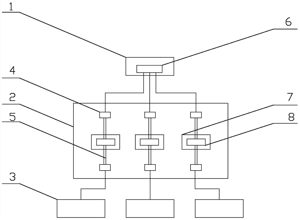
[0014] Such as figure 1 As shown, the dual-fiber long-distance optical fiber monitoring system of the present invention includes a monitoring center 1, a communication network module 2, and a monitoring station 3. The monitoring station 3 includes an optical fiber distribution frame, which is connected with an optical switch, The optical power meter is connected, the optical switch and the optical power meter are connected to the optical time domain reflectometer, and the optical time domain reflectometer is connected to the communication network module 2; the optical fiber distribution frame is connected to multiple optical fiber lines and 3 monitoring stations The number is 3-10. The optical fiber distribution frame includes the installation frame and the optical fiber tray, which are installed in the optical fiber distribution frame. The communication network module 2 includes the optical fiber 4 and the optical fiber 5. The optical fiber 4 is located in the monitoring center...


PUM


Abstract

The invention provides a dual-optical fiber looped optical fiber monitoring system, which belongs to the field of power monitoring equipment. The system comprises a monitoring center, a communication network module and monitoring stations, wherein each monitoring station comprises an optical fiber distribution frame; the optical fiber distribution frame is respectively connected with an optical switch and an optical power meter; the optical switch and the optical power meter are connected with an optical time domain reflector; the optical time domain reflector is connected with the communication network module; and the optical fiber distribution frame is connected with multiple optical fiber lines. The optical fiber monitoring system is a real-time and online intelligent communication quality automatic detection system which has an early warning function, and an optical fiber transmission network maintenance mode with manpower plus instruments in the prior art can be fully replaced.

Description

technical field [0001] The invention provides a dual optical fiber long-distance optical fiber monitoring system, which belongs to the field of electric power monitoring equipment. Background technique [0002] With the rapid growth of data traffic, as the transmission medium of the information highway, the role of optical fiber communication is becoming more and more important. Due to its high speed and large capacity, if the optical fiber fails and is interrupted for a long time, it will cause huge damage. loss. [0003] The defect of the current existing technology is that the generally adopted passive management and maintenance mode has obviously lagged behind the requirements for the stability of the optical fiber transmission network. Contents of the invention [0004] The purpose of the present invention is to provide an optical fiber monitoring system, which is a real-time, online intelligent communication quality automatic detection system with early warning func...

Claims


Application Information

Patent Timeline
IPC IPC(8): H04B10/077H04B10/079
Inventor 张春燕杨盛启
Owner 淄博思科电子技术开发有限公司
Why Eureka
Try Eureka