Front-end circuit for an ultrasound transducer probe

a transducer and front-end circuit technology, applied in the field of ultrasound transducer probes, can solve the problems that the process used to fabricate this integrated circuit is not able to handle the high voltage levels which are usually required and desired, and achieve the effects of increasing the penetration or signal-to-noise ratio, and increasing the number of used amplifiers

Inactive Publication Date: 2011-09-29
KONINKLIJKE PHILIPS ELECTRONICS NV
View PDF14 Cites 26 Cited by
  • Summary
  • Abstract
  • Description
  • Claims
  • Application Information

AI Technical Summary

Benefits of technology

[0009]The particular amplifiers (or pulsers) are thereby operated in a bridged mode. Each transducer element is thus connected across the output ports of two associated amplifiers and is supplied with up to twice the voltage level of the input voltage fed to said amplifiers' voltage supply terminals. Using such a circuit topology means in effect to double the number of used amplifiers. The proposed circuit makes it possible to double the amplitude level of the single-ended supply voltage at the supply port of the front-end circuit with the same IC process and further implies the advantage of obtaining a higher transmit power and therefore increased penetration or signal-to-noise ratio without needing to change the existing scanhead acoustic design and without needing to increase the amplitude level of the front-end circuit's supply voltage relative to a ground potential. Furthermore, the proposed front-end circuit allows the use of a less expensive scanhead design in case it is intended to maintain transmit power instead of increasing it or to do trade-offs between transmit power, penetration, signal-to-noise ratio and acoustic stack design and cost.

Problems solved by technology

In conventional designs of compact portable ultrasound machines which are available on the market today, the front-end circuit may be equipped with a transmitter unit implemented by an integrated circuit with given input voltage constraints prescribing a limited supply voltage, and it may be that the process used to fabricate this integrated circuit is not able to handle those high voltage levels which are usually required and desired for traditional ultrasound probes to get sufficient acoustic transmit power.

Method used


Image

  • Front-end circuit for an ultrasound transducer probe
  • Front-end circuit for an ultrasound transducer probe
  • Front-end circuit for an ultrasound transducer probe

Examples


Embodiment Construction

[0026]In the following, different embodiments of the present invention will be explained in detail with respect to special refinements and referring to the accompanying drawings.

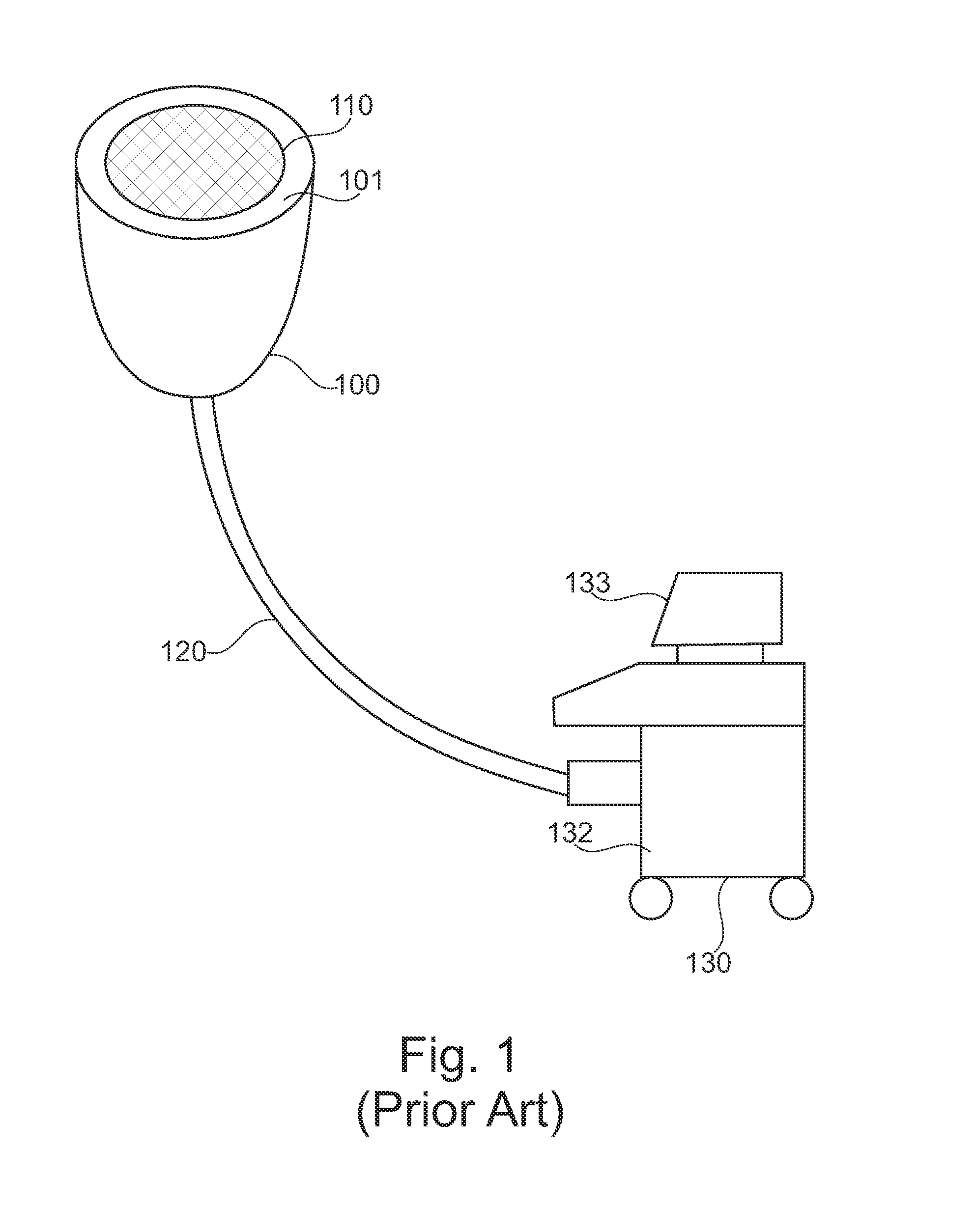
[0027]FIG. 1 depicts a conventional ultrasound system as known from WO 2006 / 035384 A1 that includes an ultrasonic transducer assembly (referred to in the art as “ultrasound transducer”, “transducer probe” or “scanhead”) 100. During an ultrasound examination, when generating sonography images, the attending physician holds an ultrasound transducer (a device that converts electrical signals into ultrasound signals to be transmitted and simultaneously receives reflected ultrasound waves) in his / her hand, places the transducer face (the scanhead or surface that emits sound waves and receives reflected sound waves) against a patient's skin and moved it over different portions of the patient's anatomy so as to obtain a set of desired sonography images. In order to ensure good contact between the transducer (someti...


PUM


Abstract

The present invention relates to an ultrasound transducer probe 100 having an array of transducer elements 110 for transmitting ultrasound transmit pulses and receiving echo signals in response to these transmit pulses. More precisely, the invention refers to a front-end circuit 300, 300′ or 300″ preconnected to such an ultrasound transducer probe, wherein said front-end circuit, which may e.g. be realized as an application-specific integrated circuit (ASIC) with given input voltage constraints prescribing a limited supply voltagein1, comprises a transmission stage 301 which includes a branched voltage control line 302 or lines with two transmit branches 302a and 302b being respectively connected to a different terminal of each transducer element 110 for providing each of these transducer elements with a differential excitation or pulse voltageop whose amplitude level is up to twice the voltage levelin1 of the single-ended front-end circuit 300, 300′ or 300″ which is supplied by voltage control line 302.

Description

FIELD OF THE INVENTION[0001]The present invention relates to an ultrasound transducer probe (scanhead) having an array of transducer elements for transmitting ultrasound transmit pulses and receiving echo signals in response to these transmit pulses. More precisely, the invention refers to a front-end circuit preconnected to such an ultrasound transducer probe, wherein said front-end circuit, which may e.g. be realized as an application-specific integrated circuit (ASIC) with given input voltage constraints prescribing a limited supply voltage, comprises a transmission stage, said transmission stage comprising a branched voltage control line or lines with two transmit branches being respectively connected to a different terminal of each transducer element for providing each of these transducer elements with a differential excitation or pulse voltage whose amplitude level is up to twice the voltage level of the single-ended front-end circuit which is supplied by said voltage control ...

Claims


Application Information

Patent Timeline
Patent Type & Authority Applications(United States)
IPC IPC(8): A61B8/14
CPCB06B1/0207A61B8/4483G01S7/5202G01S7/5208G01S7/52025
Inventor OLSSON, LARS JONASROBINSON, ANDREWBETTS, RICHARD
Owner KONINKLIJKE PHILIPS ELECTRONICS NV
Why Eureka
Try Eureka