Multi-channel Mach-Zehnder interferometer type optical circuits for restraining heat interference of adjacent channel

a multi-channel, interferometer-type technology, applied in the direction of optical light guides, optical waveguide light guides, instruments, etc., can solve the problems of difficult control of signal light quantity to a desired value, unintended temperature rise in the waveguide arm, and high cost of multi-channel mach-zehnder interferometer-type optical circuits. , to achieve the effect of reducing power consumption, reducing heat interference, and reducing heat interferen

Inactive Publication Date: 2005-05-26
NEC CORP
View PDF4 Cites 19 Cited by
  • Summary
  • Abstract
  • Description
  • Claims
  • Application Information

AI Technical Summary

Benefits of technology

[0021] In the first embodyment, the heat interference occurring with the adjacent Mach-Zehnder interferometer can be restrained to a very small extent as compared with the fluctuation due to the polarized light. Therefore, even if size of the chip is not changed, the loss fluctuation due to heat interference can be expected to be improved up to a negligible level as compared with the fluctuation due to the polarized light.
[0022] Also, in the second embodyment, in addition to the interference in the first embodyment, a number of the channels in the optical circuit can be substantially doubled without substantially changing size of the chip, and a manufacturing cost of the optical circuit per channel can be reduced by half substantially. On the other hand, since the chip becomes smaller by the multi-channel Mach-Zehnder interferometer type optical circuit being integrated at high density, variations in each channel due to differences in structural parameters (such as size of waveguide path and refractive index) can be restrained small as compared with the conventional optical circuit having the same number of channels.
[0024] In the fourth embodyment, it can be very easily achieved to restrain heat interference occurring in the Mach-Zehnder interferometer for reducing power consumption.
[0025] Through the use of the above-described methods, it is possible to minimize the heat interference while preventing the elements from becoming large-sized for achieving the problems.

Problems solved by technology

In the Mach-Zehnder interferometer in the Mach-Zehnder interferometer type optical circuit, however, by the heat generated by an adjacent temperature controller, there occurs unintended temperature rise in the waveguide arm.
Therefore, there is a problem that there are few Mach-Zehnder interferometers in number to be provided on one chip and the multi-channel Mach-Zehnder interferometer type optical circuit becomes expensive.
Further, since this Mach-Zehnder interferometer type optical circuit has great heat interference with the adjacent channel by heat 4 to be generated by the temperature controller 3, there is also a problem that it is difficult to control quantity of light of the signal light to a desired value.
Also, in the conventional multi-channel Mach-Zehnder interferometer type optical circuit shown in FIG. 1, the heat to be generated from the temperature controller 1 causes heat interference (or heat cross talk), that affects the adjacent Mach-Zehnder interferometer, resulting in worsen controllability of the Mach-Zehnder interferometer of each channel or fluctuation in intensity of output light.
Therefore, by the first means, the entire circuit cannot be miniaturized, nor can high-density integration be made.
However, since this Mach-Zehnder interferometer type optical circuit has also large areas of portions having no pattern of waveguide path, size of elements becomes noticeably large-sized with an increase in number of channels and the Mach-Zehnder interferometer type optical circuit cannot be integrated at high density.
However, since fluctuation due to polarized light results from a cause different from that of fluctuation due to heat interference, fluctuation of loss of about ±1 [dB] at maximum obtained by summing up both can occur.
Also, when the width of the groove 11(a-b) is narrowed, heat 12 transfers to the adjacent Mach-Zehnder interferometer by radiation as shown in FIG. 4 to cause heat interference, and therefore, it is difficult to independently control the Mach-Zehnder interferometer for each channel.
As described above, conventionally it has been difficult to solve two problems: high-density integration of optical elements and elimination of influence of heat interference simultaneously.

Method used


Image

  • Multi-channel Mach-Zehnder interferometer type optical circuits for restraining heat interference of adjacent channel
  • Multi-channel Mach-Zehnder interferometer type optical circuits for restraining heat interference of adjacent channel
  • Multi-channel Mach-Zehnder interferometer type optical circuits for restraining heat interference of adjacent channel

Examples


Embodiment Construction

[0048] The description will be made of a preferred example of the Mach-Zehnder interferometer type optical circuit according to the present invention.

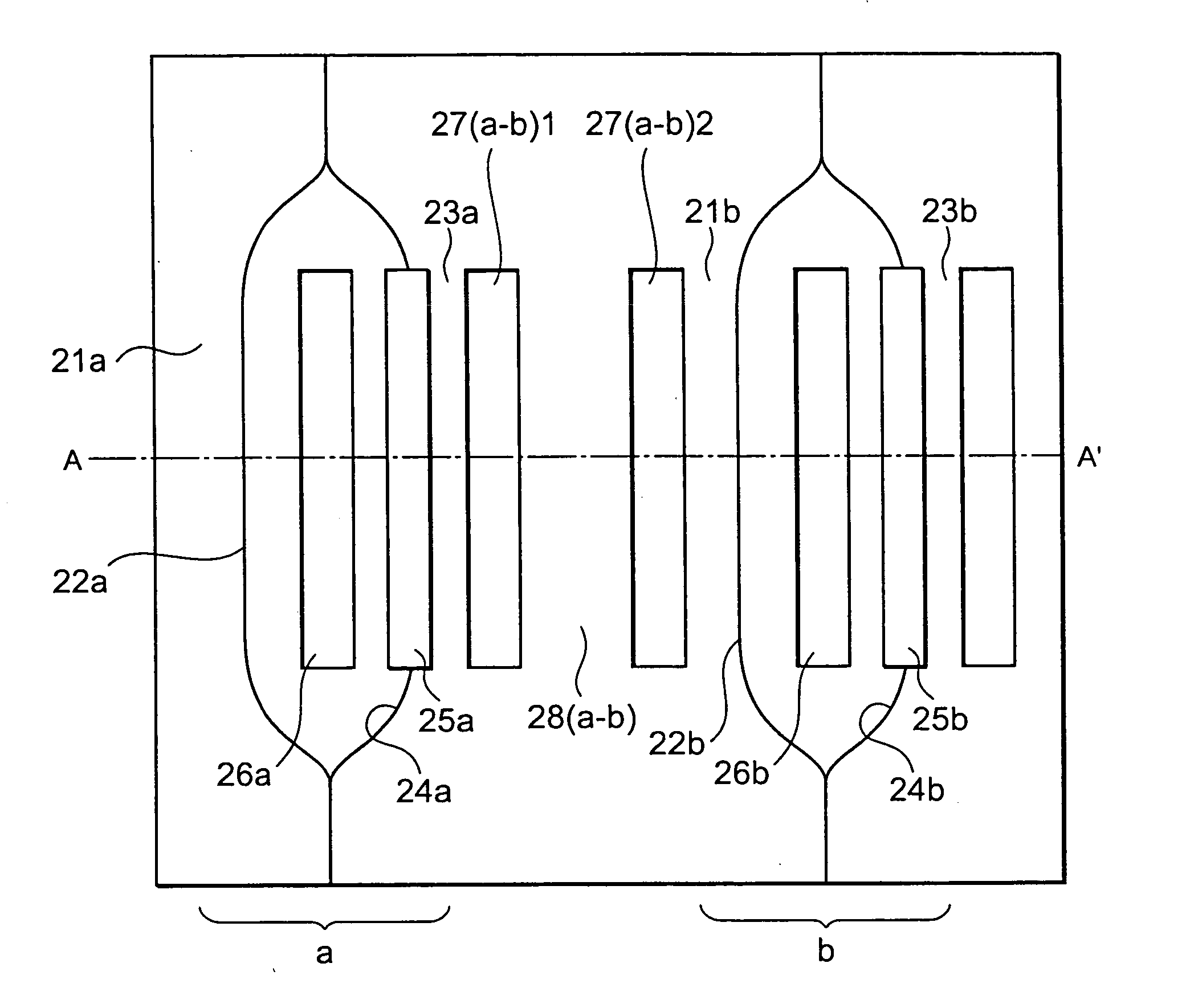
[0049] Hereinafter, the description will be made of the Mach-Zehnder interferometer type optical circuit shown in FIGS. 5a and 5b. FIG. 5a is a plan view showing the Mach-Zehnder interferometer type optical circuit according to the present example, showing two Mach-Zehnder interferometers a, b. FIG. 5b is a cross-sectional view taken on line A-A′ of FIG. 5a. Reference numeral 21a, 23a designates a cladding layer of a waveguide arm of a Mach-Zehnder interferometer a; 22a, 24a, a core of the waveguide arm of the Mach-Zehnder interferometer a; 25a, a temperature controller; and 26a, a groove between two waveguide arms. Reference numeral 21b, 23b designates a cladding layer of a waveguide arm of a Mach-Zehnder interferometer b; 22b, 24b, a core of the waveguide arm of the Mach-Zehnder interferometer b; 25b, a temperature controller; and 2...


PUM

PropertyMeasurementUnit
distanceaaaaaaaaaa
thicknessaaaaaaaaaa
lengthaaaaaaaaaa

Abstract

In the Mach-Zehnder interferometer type optical circuit in which a plurality of Mach-Zehnder interferometers have been provided, between the Mach-Zehnder interferometers a and b, there are provided a plurality of grooves 27(a-b)1, 27(a-b)2 and an endothermic wall 28(a-b). Since heat generated from the temperature control device 25a mounted on the waveguide arm of the Mach-Zehnder interferometer a is absorbed by the endothermic wall 28(a-b), an influence due to heat interference to be exerted on the Mach-Zehnder interferometer b is restrained.

Description

FIELD OF THE INVENTION [0001] The present invention relates to a multi-channel Mach-Zehnder interferometer type optical circuit, and more particularly to a multi-channel Mach-Zehnder interferometer type optical circuit miniaturized and highly integrated as compared with the prior art for restraining an influence of heat interference. DESCRIPTION OF THE RELATED ART [0002] A Wavelength Division Multiplexing (WDM) communication system is a system for generally multiplexing a plurality of optical signals having different wavelength with Arrayed Waveguide Grating (AWG) for transmission. In this case, transmission paths different every the above-described plurality of optical signals are called channels. [0003] In the present WDM communication system, as the demand for transmission capacity grows, it is required that optical signals be transmitted through much more channels than in the conventional WDM communication system. Length of a transmission path through which an optional signal tr...

Claims


Application Information

Patent Timeline
Patent Type & Authority Applications(United States)
IPC IPC(8): G02F1/01G02B6/122G02F1/225
CPCG02F1/225G02F1/0147
Inventor TAKAHASHI, MORIO
Owner NEC CORP
Why Eureka
Try Eureka