Radio communication method, radio communication system, base station, and mobile station

a radio communication system and radio communication technology, applied in the field of radio communication methods, can solve the problems of increasing the ratio of desired signal power to interference signal power (sir), occurrence of bit determination errors, and increasing the loss of radio signal propagation, so as to reduce the power of control signal on a downlink, increase the amount of power that can be used for other downlinks, and increase the throughput of downlinks

Inactive Publication Date: 2009-06-25
NEC CORP
View PDF9 Cites 29 Cited by
  • Summary
  • Abstract
  • Description
  • Claims
  • Application Information

AI Technical Summary

Benefits of technology

[0008]However, the following three controls are necessary for maintaining the above-described control signals at a desired reception quality regardless of the propagation path conditions:(1) Using high transmission power to improve SIR in the transmission and reception of control signals to a mobile station in which the propagation path environment has deteriorated.(2) Using a high spreading rate or strong coding to increase the transmission time for transmitting control signals in the transmission and reception of control signals to a mobile station in which the propagation path environment has deteriorated.(3) Using a high spreading rate or strong coding to increase the frequency bandwidth for transmitting control signals in the transmission and reception of control signals to a mobile station in which the propagation path environment has deteriorated.

Problems solved by technology

In a radio communication system, propagation loss of a radio signal increases with increasing distance between a base station and mobile station.
Thus, in a mobile station located in the vicinity of a cell boundary, the ratio of the desired signal power to interference signal power (SIR) deteriorates dramatically compared to that of a mobile station located in the center of a cell due to both the decrease in the desired signal power and the increase in interference power resulting from the decreasing distance from adjacent base stations.
Deterioration in SIR tends to bring about the occurrence of bit determination errors and in some cases prevents communication due to the increase in the data block reception error rate.

Method used


Image

  • Radio communication method, radio communication system, base station, and mobile station
  • Radio communication method, radio communication system, base station, and mobile station
  • Radio communication method, radio communication system, base station, and mobile station

Examples


first exemplary embodiment

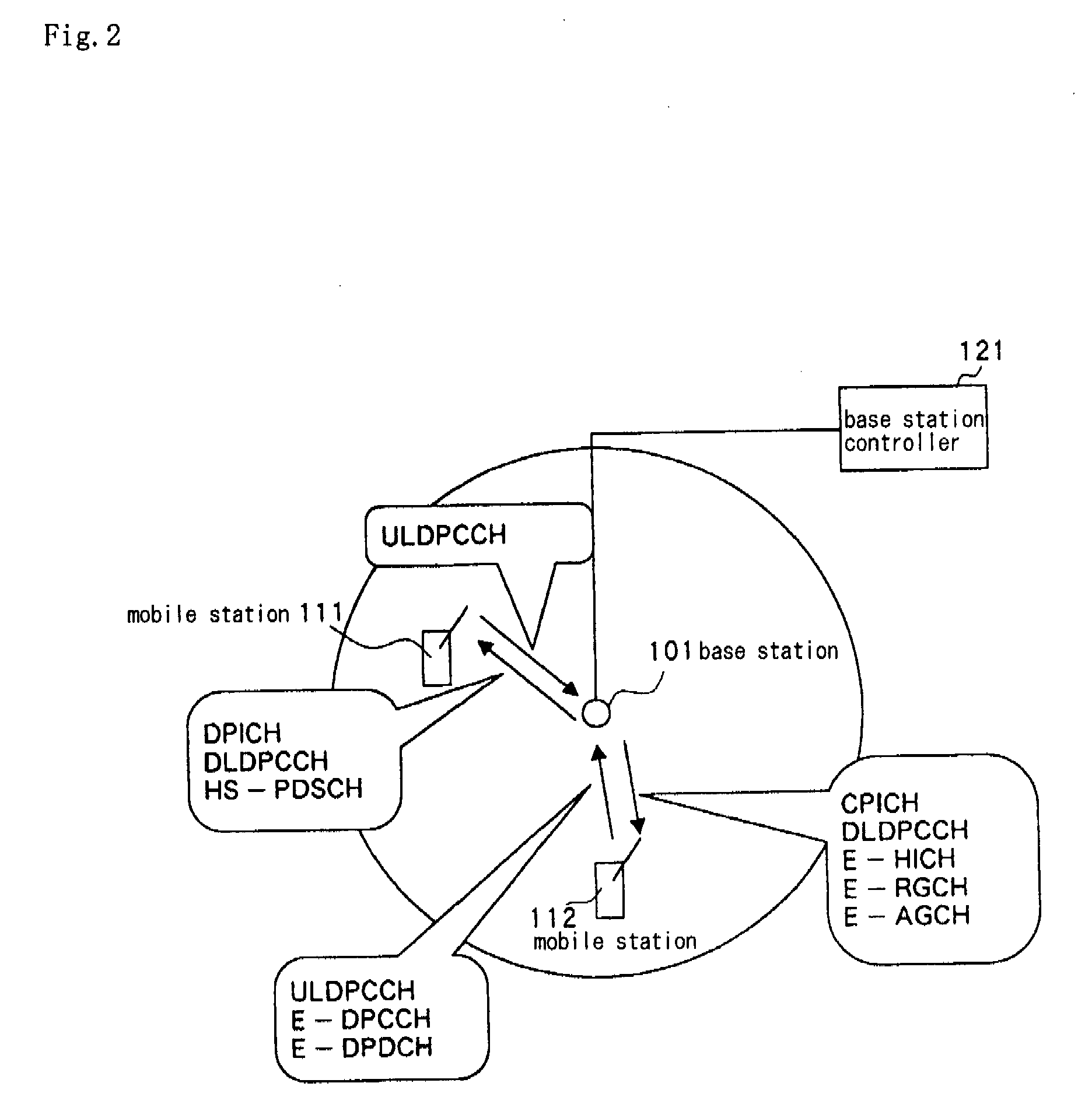
[0046]FIG. 2 shows the radio communication system that is the first exemplary embodiment of the present invention. The example here described is EUDCH (Enhanced Uplink Dedicated Channel), which is a method of high-speed packet transmission on a 3GPP uplink.

[0047]Referring to FIG. 2, the radio communication system is a system that employs the (UL (uplink) data transmission / DL (downlink) control channel / pilot determination / base station determination / bit number alteration) construction of the first embodiment and is made from: base station 101, a plurality of mobile stations 111 and 112, and base station controller 121 to which base station 101 is connected. Base station 101 transmits a pilot channel (CPICH: Common Pilot Indicator Channel), which is a known signal, to all mobile stations in the cell at a fixed power.

[0048]Base station 101 and mobile station 111 set individual control channels (DPCCH: Dedicated Physical Control Channels) on uplinks and downlinks, and set an HS-PDSCH (Hi...

second exemplary embodiment

[0078]The radio communication system that is the second exemplary embodiment of the present invention employs the construction (UL data transmission / DL control channel / separate channel power determination / base station determination / bit number alteration) of the first embodiment. The radio communication system of the first exemplary embodiment is of a configuration in which a mobile stations measures common pilot signal reception quality and reports to the base station in order to estimate the downlink propagation paths. In contrast, the radio communication system of the present embodiment differs from the first exemplary embodiment in that, instead of this estimation of downlink propagation paths, the propagation paths of a mobile stations are estimated from the DPCCH transmission power for which closed-loop transmission power control is implemented to attain a prescribed reception quality.

[0079]The construction of the radio communication system of the present embodiment is next des...

third exemplary embodiment

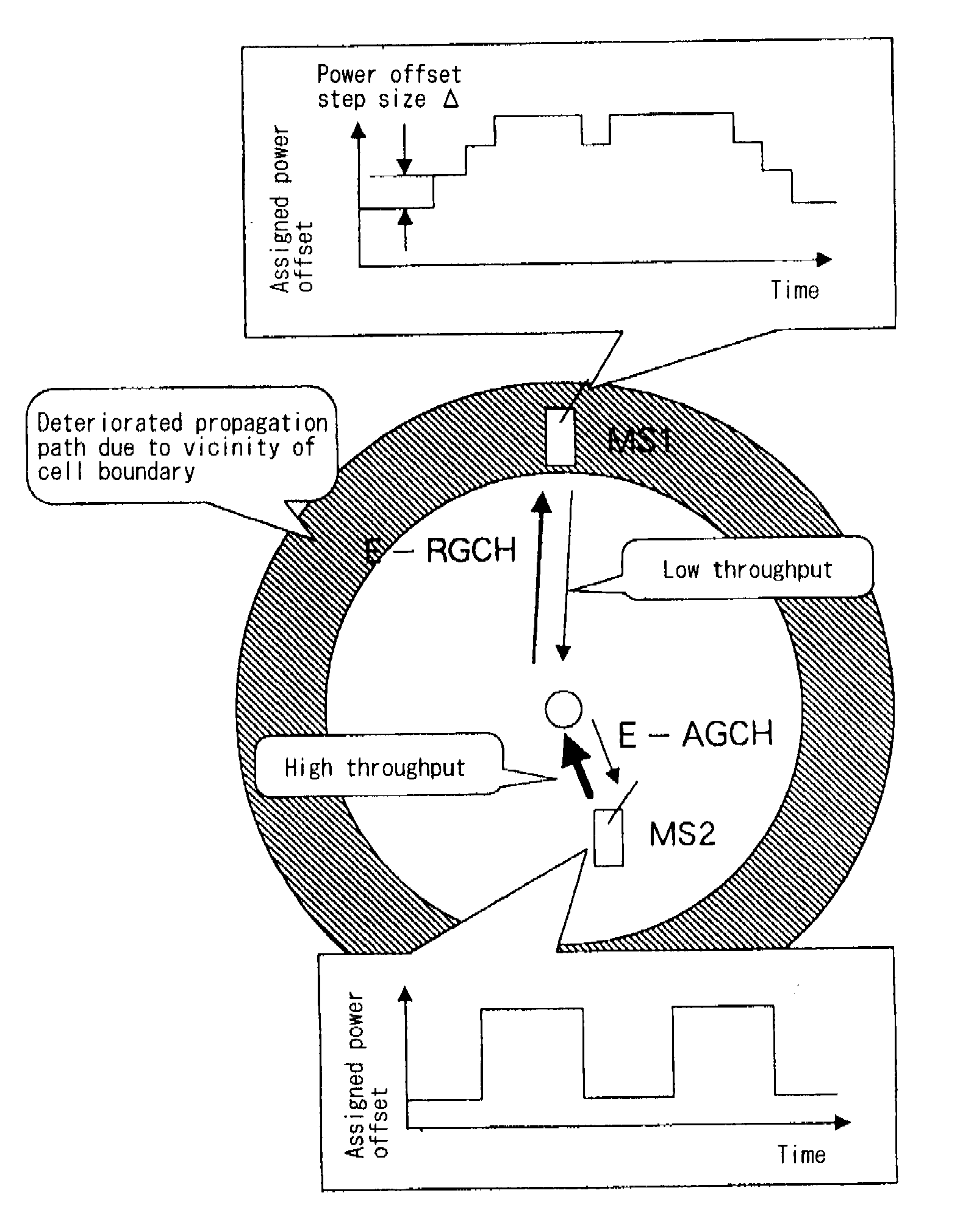
[0082]The radio communication system that is the third exemplary embodiment of the present invention employs the construction (UL data transmission / DL control channel / pilot determination / base station determination / shared number alteration) of the third embodiment. The radio communication system of the first exemplary embodiment is of a configuration that uses E-RGCH in which the number of information bits is less than in E-AGCH to reduce the control signal transmission power of downlinks for a mobile station having poor propagation paths. In contrast, the radio communication system of the present embodiment differs from the first exemplary embodiment in that, instead of using E-RGCH to reduce the control signal transmission power of downlinks for a mobile station in which the propagation path is poor, common scheduling information is transmitted by E-AGCH to a plurality of mobile stations for which propagation path conditions are poor.

[0083]The following explanation regards the conf...


PUM


Abstract

A radio communication method is provided for reducing the overhead of radio resources (transmission power, transmission time, frequency band) caused by the transmission of a control signal to a mobile station in a poor propagation environment and thus enabling an improvement of throughput of the entire system. A base station (101) and mobile stations (111 and 112) are connected to allow communication by way of radio links in which a control channel and data channel can be set on each of downlinks and uplinks. The base station (101) uses the control channel to transmit a control signal to the mobile stations (111 and 112). The mobile stations (111 and 112), based on the control signal received from the base station (101), use a data channel to transmit or receive data. The base station (101) alters the amount of information of the control signal in accordance with communication conditions of the propagation paths of the radio links formed with the mobile stations (111 and 112).

Description

TECHNICAL FIELD[0001]The present invention relates to a radio communication method for performing high-speed packet transmission. The present invention further relates to a radio communication system, base station and mobile station that adopt a radio communication method of this type.BACKGROUND ART[0002]In a radio communication system, propagation loss of a radio signal increases with increasing distance between a base station and mobile station. Thus, in a mobile station located in the vicinity of a cell boundary, the ratio of the desired signal power to interference signal power (SIR) deteriorates dramatically compared to that of a mobile station located in the center of a cell due to both the decrease in the desired signal power and the increase in interference power resulting from the decreasing distance from adjacent base stations. Deterioration in SIR tends to bring about the occurrence of bit determination errors and in some cases prevents communication due to the increase i...

Claims


Application Information

Patent Timeline
Patent Type & Authority Applications(United States)
IPC IPC(8): H04W72/04H04B7/00H04W28/06
CPCH04B7/2656H04W28/06H04L1/003H04L1/0002H04W52/241H04W52/325H04W28/0236
Inventor KURODA, NAHOKO
Owner NEC CORP
Why Eureka
Try Eureka