

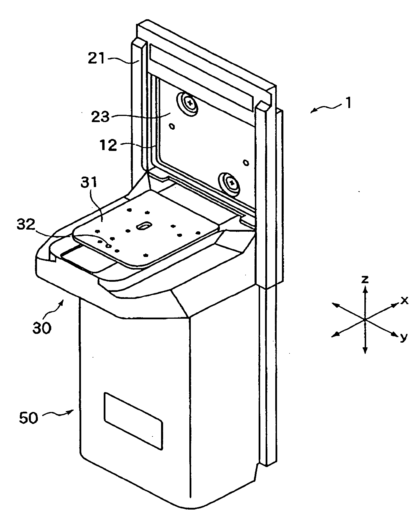
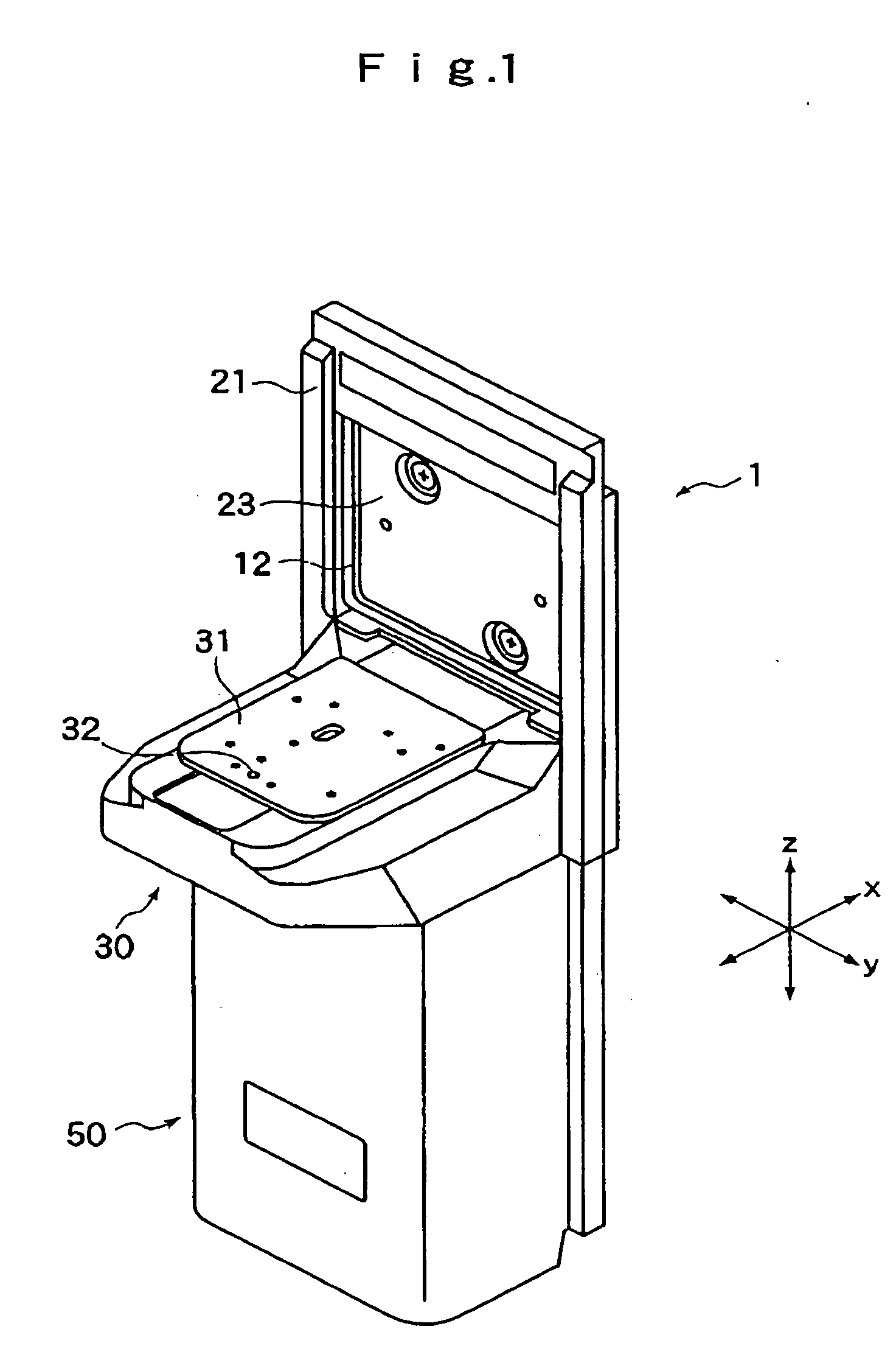
Container Opening-Closing Apparatus and Container-Placement-Position Adjustment Method for the Same
a technology for opening and closing containers and container containers, which is applied in the direction of de-stacking articles, charge manipulation, furnaces, etc., can solve the problems of increasing cost, complex transfer apparatus, and large volume, and achieve the effect of increasing cost and lengthening the transfer time of the wafer carrier
- Summary
- Abstract
- Description
- Claims
- Application Information
AI Technical Summary
Benefits of technology
Problems solved by technology
Method used
Image

Examples
embodiment 1
Alignment Operation of Embodiment 1
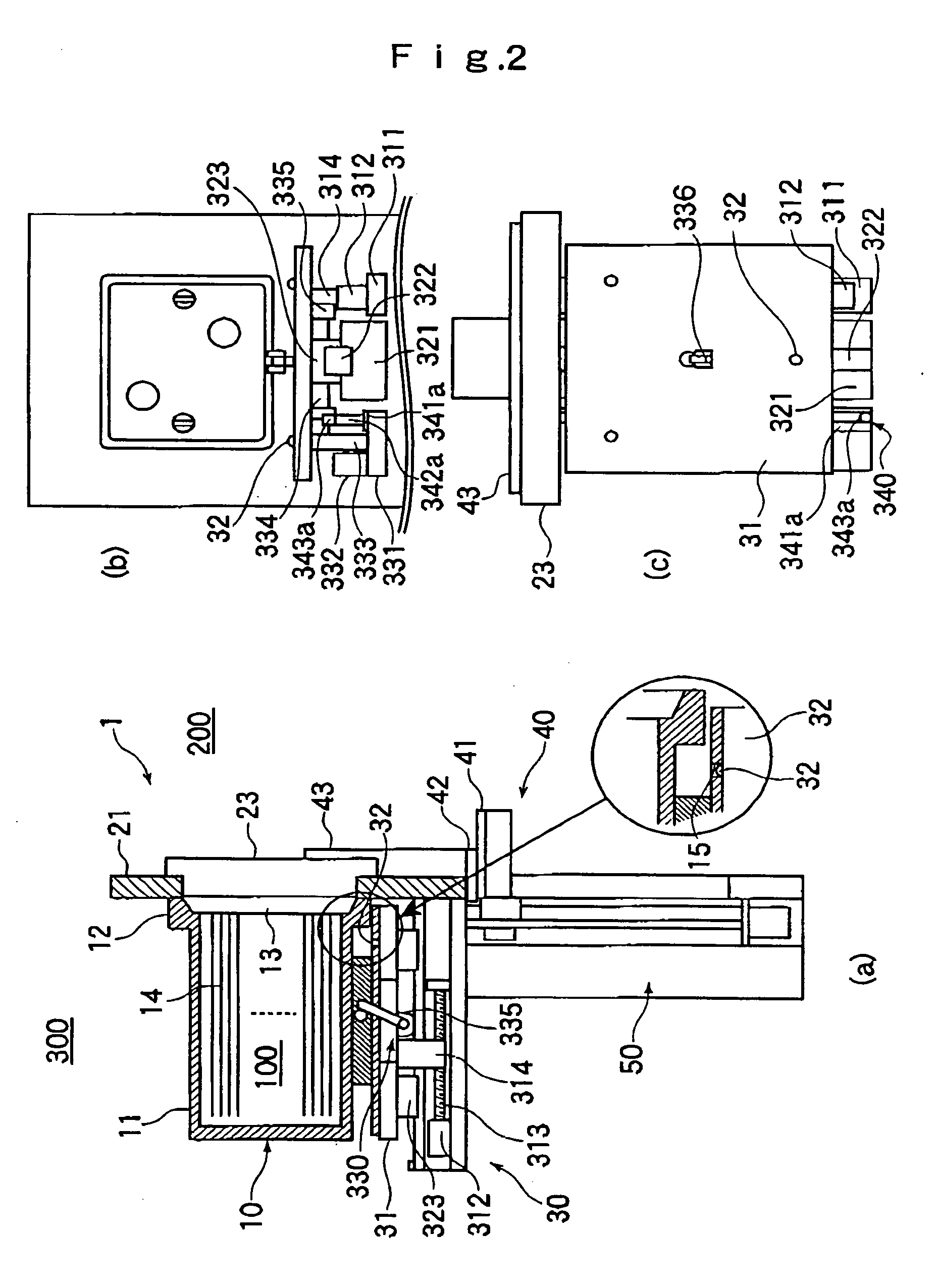
[0063] Next, operation of establishing alignment between the positioning grooves 15 of the FOUP 10 and the positioning pins 32 of the dock plate 31 in Embodiment 1 will be described with reference to FIGS. 7 and 9.
[0064] When the FOUP 10 reaches a point above the FOUP opener 1 as a result of conveyance by the unillustrated conveying apparatus, signal checking is performed between the conveying apparatus and the FOUP opener 1.
[0065] On the basis of the checked signal, there are read data stored in a storage section 61 and regarding the transport position of the dock plate 31 (data regarding the transport position of the dock plate 31 for each conveying apparatus, which data are stored at the time of installation of the FOUP opener 1, which will be described later).
[0066] A control means 60 drives and controls the dock-moving motor 312 of the dock-moving mechanism 30 on the basis of the read data so as o move the dock plate 31 to the transfer posi...
embodiment 2
Alignment Operation of Embodiment 2
[0091] Next, operation of establishing alignment between the positioning grooves 15 of the FOUP 10 and the positioning pins 32 of the dock plate 31 in Embodiment 2 will be described with reference to FIGS. 8(a) to (c) and FIG. 10.
[0092] When the FOUP 10 is not placed on the dock plate 31, the dock plate 31 stands by at the FOUP transfer position (position apart from the port plate 21). At this time, the detection sensors 343a and 343b check the FOUP transfer position and the work position of the dock plate 31.
[0093] Next, the FOUP 10 is conveyed to the FOUP opener 1 by the unillustrated conveying apparatus, and the conveying apparatus stops generally above the dock plate 31. After stoppage, signal communication is performed between the conveying apparatus and the FOUP opener 1, and position data of the dock plate 31 matching the conveyance apparatus which performs transfer (data regarding the transport position of the dock plate 31 for each conve...
embodiment 3
[0119] Next, an embodiment in which the cam mechanism shown in FIG. 13 is used as a dock plate moving mechanism will be described in detail as Embodiment 3 with reference to FIG. 14.
[0120] Embodiment 3 differs from Embodiment 1 (see FIG. 2) in that, in place of the ball screw, a cam mechanism is used in a moving mechanism portion of the dock-moving mechanism 30. Since the remaining components are the same, they are denoted by the same names and reference numerals, and their detailed description will not be repeated.
[0121] In the dock-moving mechanism 30 of FIG. 14, a dock-moving motor 512 is fixedly mounted on the lower surface of the base 311, and an unillustrated cut hole is formed in the base 311 so as to enable the output shaft 513 of the dock-moving motor 512 to vertically penetrate the base 311. One end of an arm-shaped transmission member 514 is fixed to the output shaft 513, and a cam follower 516 is rotatably attached to the other end of the transmission member 514. This ...
PUM
 Abstract
Description
Claims
Application Information