Internal force reinforcement device for pillar structure

A technology for strengthening devices and columns, applied in the direction of columns, pier columns, pillars, etc., can solve the problems of maintenance management and dismantling convenience, difficulty in forming cohesive force, and construction convenience, etc., to improve construction and maintenance The convenience of management and disassembly, and the effect of improving performance

Inactive Publication Date: 2015-06-17
INDUSRTY ACADEMIC COOPERATION FOUND CHOSUN UNIV
View PDF7 Cites 2 Cited by
  • Summary
  • Abstract
  • Description
  • Claims
  • Application Information

AI Technical Summary

Problems solved by technology

[0009] However, with such an internal force reinforcing material and a steel cord structure reinforcing system and method thereof, since the bonded area of ​​the steel cord is formed on one area in the circumferential area of ​​the column structure, it is difficult to form a certain amount on the entire circumferential area of ​​the column structure. The problem of adhesion
[0010] As a result, each internal force reinforcement material is in close contact with the circumferential surface of the column structure with different pressures, and there is a problem that the improvement of the internal force reinforcement performance of the column structure is limited.
[0011] In addition, in view of further improvement of reinforcement performance, prevention of exposure and corrosion of internal reinforcement materials and wire ropes, etc., and appearance, it is necessary to form a protective layer such as mortar, so there are constructions due to the increase of mortar for forming the protective layer and according to the maintenance process. The problem that the convenience of construction is reduced due to reasons such as the construction process and the increase in the construction period
[0012] In addition, when maintenance, management, or disassembly of the internal force reinforcement material etc. is required, the protective layer needs to be removed, so there is a problem that the convenience of maintenance management and disassembly is reduced.

Method used


Image

  • Internal force reinforcement device for pillar structure
  • Internal force reinforcement device for pillar structure
  • Internal force reinforcement device for pillar structure

Examples


Embodiment Construction

[0058] Hereinafter, various embodiments of the present invention will be described in detail with reference to the drawings. At this time, the same components of the embodiment are denoted by the same reference numerals.

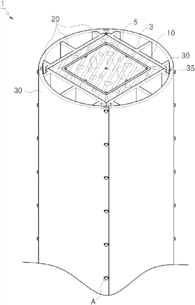
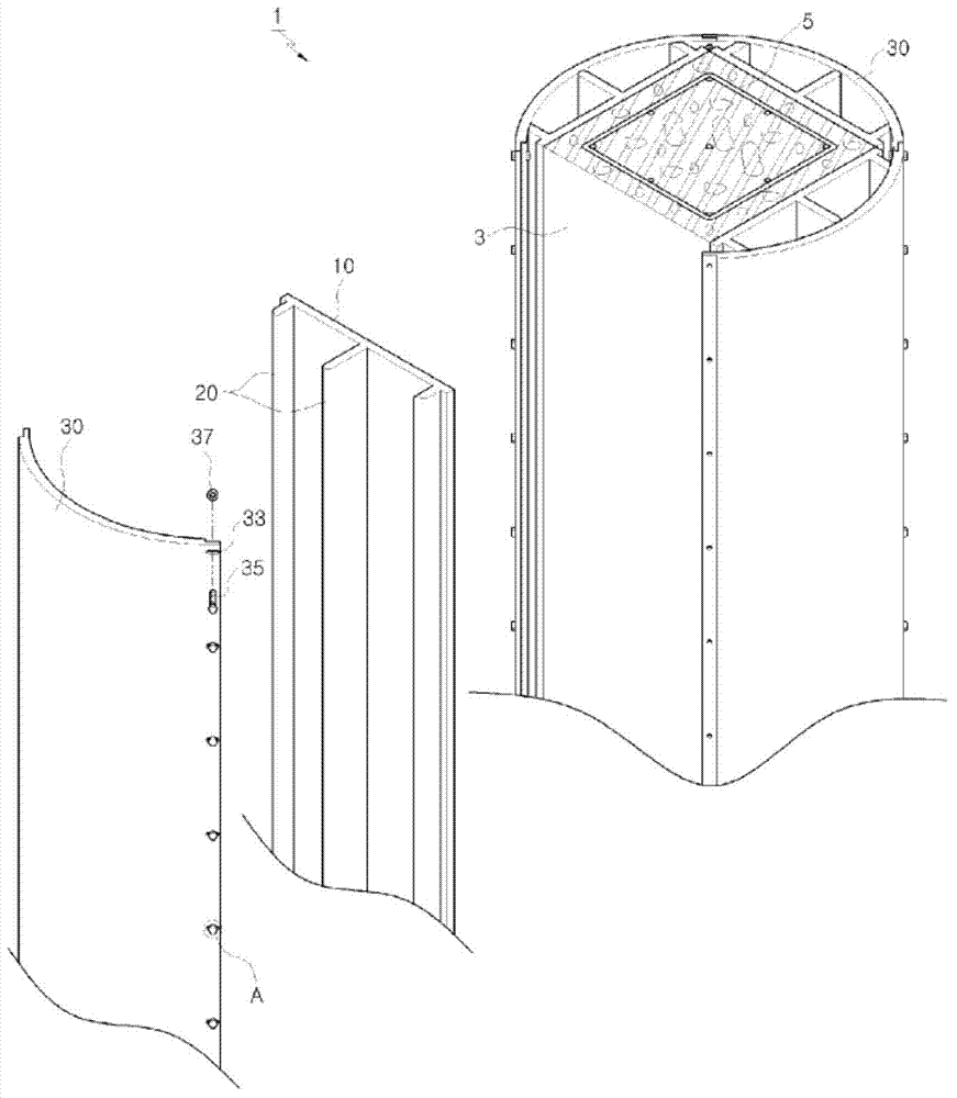
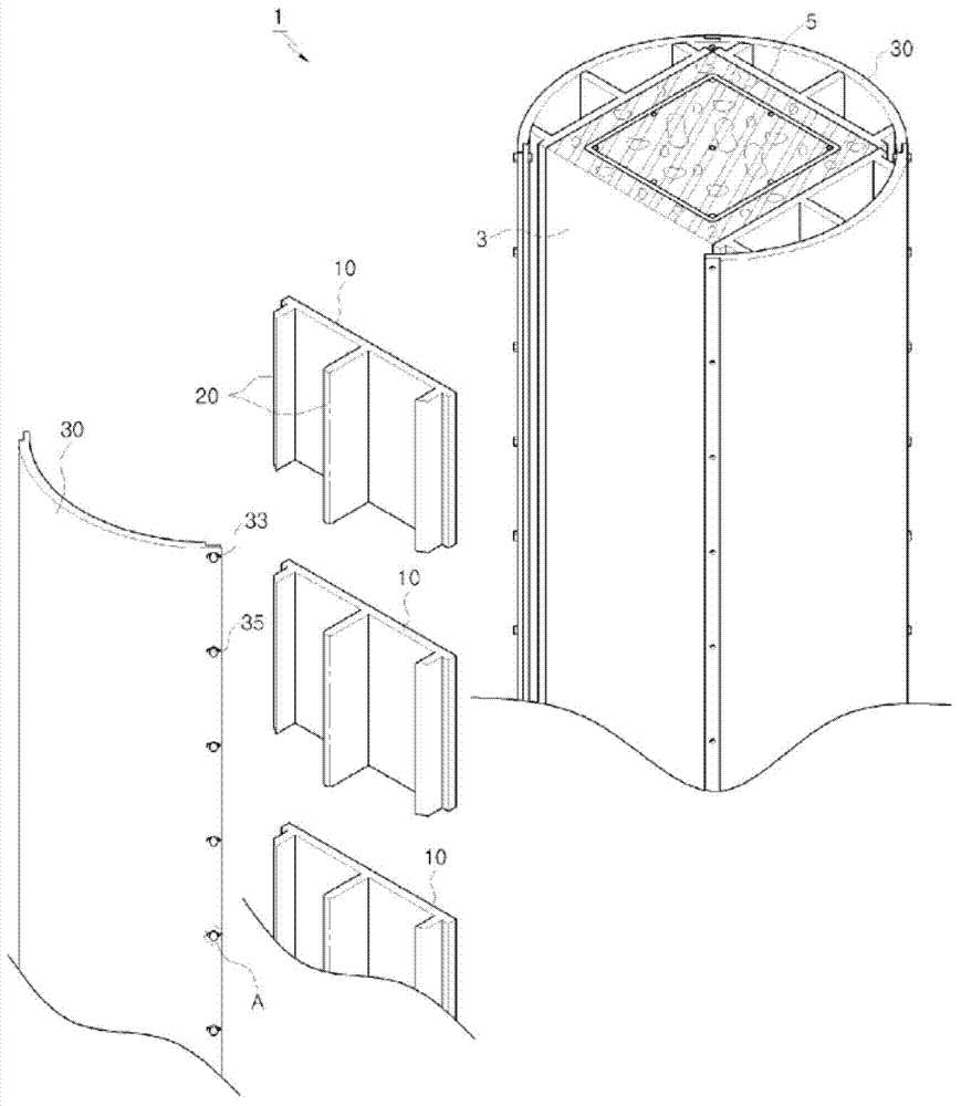
[0059] Such as Figure 1 to Figure 9 As shown, the internal force strengthening device 1 of the column structure of the first embodiment of the present invention includes: a plurality of internal reinforcement plates 10, which form a pressurized surface on the circumferential surface of the column 3; The above-mentioned pressurized force transmitted by the outer reinforcing plate 30 is transmitted to the inner reinforcing plate 10;

[0060] Each inner reinforcing plate 10 is composed of plate-shaped members spaced at least a predetermined distance along the peripheral surface of the pillar 3 and contacting the peripheral surface of the pillar 3 . Here, the column 3 may be a column in which the reinforcing bar 5 is embedded or a column in which no reinforci...


PUM


Abstract

The present invention relates to an internal force reinforcement device for a pillar structure, including: a plurality of inner reinforcement plates that wrap around a circumferential surface of the pillar; at least one pair of outer reinforcement plates that are coupled to each other to wrap around an outer wall of the pillar so as to be separated from the inner reinforcement plates; and a pressure control member that is arranged on the outer reinforcement plate to put pressure or release pressure on the inner reinforcement plate to or from the pillar side. In this manner, the internal force reinforcement performance of the pillar structure is improved and at the same time, convenience in terms of construction, maintenance and repair, and disassembly is significantly improved.

Description

technical field [0001] The present invention relates to an internal force strengthening device for a column structure, and in more detail, relates to an internal force strengthening device for a column structure that can significantly improve the convenience of construction, maintenance management, and disassembly while improving the internal force strengthening performance of the column structure. Background technique [0002] In the reinforced concrete (RC, Reinforced concrete) column structure in a general building, steel bars for strengthening structural performance are embedded in the interior along the vertical and horizontal directions. However, it is difficult to ensure the safety of buildings from strong winds accompanied by earthquakes or super typhoons only relying on simple vertical and horizontal reinforcement structures. [0003] In this regard, Korean Authorized Patent No. 10-0763534 and the like disclose a method for strengthening the internal force of a colu...

Claims


Application Information

Patent Timeline
IPC IPC(8): E04C3/30
CPCE04C3/36
Inventor 崔宰赫
Owner INDUSRTY ACADEMIC COOPERATION FOUND CHOSUN UNIV
Why Eureka
Try Eureka