Glass cement gun

A glass glue gun, glass glue technology, applied in the direction of coating, the device for coating liquid on the surface, etc., can solve the problems of production cost, high use cost, increasing the weight of the glass glue gun, uneven thickness of the glass glue, etc. Achieve the effect of low production cost, light weight and low cost

Inactive Publication Date: 2015-06-24
许江永
View PDF7 Cites 0 Cited by
  • Summary
  • Abstract
  • Description
  • Claims
  • Application Information

AI Technical Summary

Problems solved by technology

The electric glass glue gun is a kind of glass glue gun that relies on the motor to drive the glue gun to advance or retreat. Its advantage is that the force is uniform, the thickness of the glass glue extruded is uniform, and the speed is consistent; the disadvantage is that the site must be equipped with a power supply or Equipped with a battery, which increases the weight of the glass glue gun itself, which is labor-intensive and inconvenient to use; secondly, the production cost and use cost are high
[0003] Pneumatic glass glue gun is a glass glue gun that relies on air pressure to push the push rod of the glass glue gun forward or backward. Although its production cost has advantages over electric glass glue guns, it still has the disadvantage of being limited by conditions. It not only requires the use of The venue must have a power supply, and an air compressor is required to provide power, which is expensive and inconvenient
[0004] Manual glass glue gun is a glass glue gun that the user pushes the push rod of the glass glue gun forward or backward through the grip of the hand. Its advantage is that it is not limited in use and the price is cheap; the disadvantage is that the thickness of the extruded glass glue is not uniform. , the speed is inconsistent and the labor intensity is high, the work efficiency is low, and it is inconvenient

Method used


Image

  • Glass cement gun
  • Glass cement gun
  • Glass cement gun

Examples


Embodiment Construction

[0023] The present invention is described in detail below in conjunction with accompanying drawing and specific embodiment:

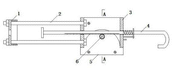
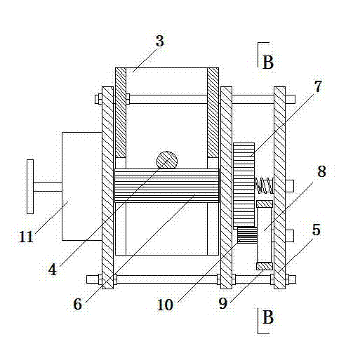
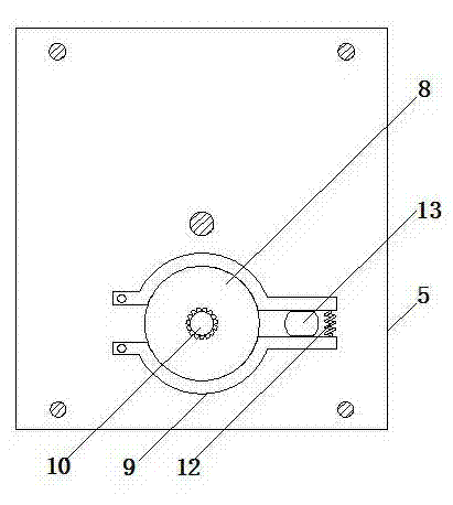
[0024] Such as figure 1 , figure 2 , image 3 Figure 4 , Figure 5 , Figure 6 As shown, the glass glue gun of the present invention includes a fixed mount 5, a glass glue tube frame, a push rod 4, a transmission gear rod 6, a push rod frame 3, a scroll spring box 11 and a brake. The glass rubber tube frame is provided with a glass rubber tube fixing card for placing or fixing the glass rubber tube, and the glass rubber tube frame is fixedly connected with one end of the push rod frame 3 . The push rod 4 is placed in the push rod frame 3 and the top end stretches into the rear of the glass rubber tube in the glass rubber tube fixing card of the glass rubber tube frame, and the end stretches out of the push rod frame 3. The bottom surface of the push rod 4 is provided with teeth for use To squeeze the glass glue in the glass glue cylinder forward...


PUM


Abstract

The invention discloses a glass cement gun which comprises a fixed rack, a glass cement cylinder rack, a push rod, a transmission gear rod, a push rod rack, a volute spiral spring box and a brake, wherein the glass cement cylinder rack is provided with a glass cylinder fixing clip, and the glass cement cylinder rack is fixedly connected with one end of the push rod rack; teeth are arranged on the bottom face of the push rod for extruding glass cement in the glass cement cylinder forwards; the transmission gear rod is intersected with the push rod and the teeth of the transmission gear rod are engaged with the teeth on the bottom face of the push rod; the front end or the back end of the transmission gear rod is fixedly connected with a volute spiral spring in the volute spiral spring box and a handle is arranged at the tail end of the front end or the back end; the push rod rack is placed in the fixed rack and the front end or the back end is connected with the fixed rack through a bolt or a hinge; the volute spiral spring box is fixedly connected with the fixed rack; the brake is connected with the transmission gear rod. The glass cement gun disclosed by the invention is light and convenient to operate, low in labor intensity, high in work efficiency and low in cost.

Description

technical field [0001] The invention relates to a tool for cutting ceramic tiles, in particular to a glass glue gun. Background technique [0002] Existing glass glue guns in industries such as construction, decoration, advertisement mainly contain three types: electric glass glue guns, pneumatic glass glue guns and manual glass glue guns. The electric glass glue gun is a kind of glass glue gun that relies on the motor to drive the glue gun to advance or retreat. Its advantage is that the force is uniform, the thickness of the glass glue extruded is uniform, and the speed is consistent; the disadvantage is that the site must be equipped with a power supply or Equipped with a storage battery, the weight of the glass glue gun is increased, and the use is labor-intensive and inconvenient; secondly, the production cost and the use cost are high. [0003] Pneumatic glass glue gun is a glass glue gun that relies on air pressure to push the push rod of the glass glue gun forward o...

Claims


Application Information

Patent Timeline
Patent Type & Authority Applications(China)
IPC IPC(8): B05C17/01
Inventor 许江永
Owner 许江永
Why Eureka
Try Eureka