
Chain transmission type lifting pallet changer

A workbench, transmission type technology, applied in manufacturing tools, metal processing equipment, welding equipment, etc., can solve problems such as poor hydraulic cylinder sealing, workbench deflection problems, and easily damaged workbench components, etc. Synchronization problem, solving complex structure, cost saving effect

Inactive Publication Date: 2015-06-24
苏州汇能激光科技有限公司
View PDF11 Cites 2 Cited by
  • Summary
  • Abstract
  • Description
  • Claims
  • Application Information

AI Technical Summary

Problems solved by technology

[0003] ①The hydraulic lifting exchange table has the problem of multi-cylinder synchronization, that is, the hydraulic cylinders are not synchronized due to the different speeds in the liquid transportation, resulting in the deflection of the worktable during lifting and lowering, which is easy to damage the components of the workbench; in addition, there are hydraulic cylinders Leakage problem, that is, the hydraulic cylinder is driven by fluid, and the sealing device will be worn out during the long-term lifting process, resulting in poor sealing of the hydraulic cylinder and leakage;
[0004] ②Dual-motor-driven lifting and exchanging workbench is driven by different motors for the front and rear axes, resulting in a problem of asynchrony between the two motors, and the workbench will tilt during the lifting process;
[0005] ③Single-motor gear drive chain synchronous lift and exchange workbench The single-motor drive of the table eliminates the synchronization problem, but with gear drive, the chain synchronization structure is relatively complicated and the cost is high

Method used


Image

  • Chain transmission type lifting pallet changer
  • Chain transmission type lifting pallet changer
  • Chain transmission type lifting pallet changer

Examples


Embodiment Construction

[0029] The following will clearly and completely describe the technical solutions in the embodiments of the present invention with reference to the drawings in the embodiments of the present invention.

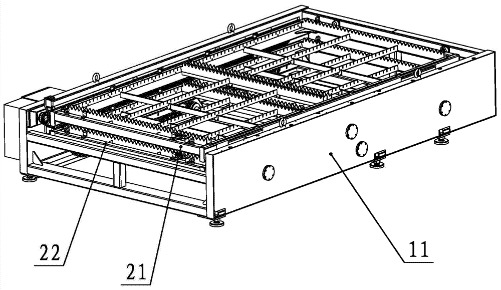
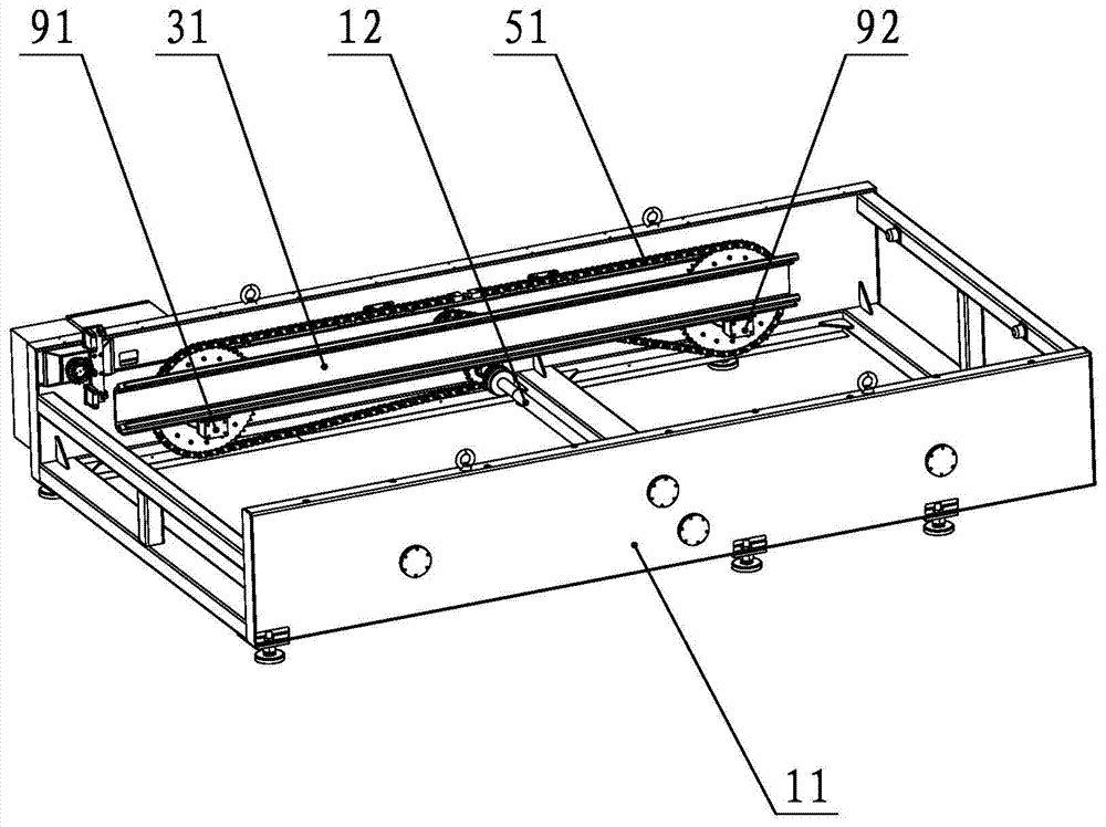
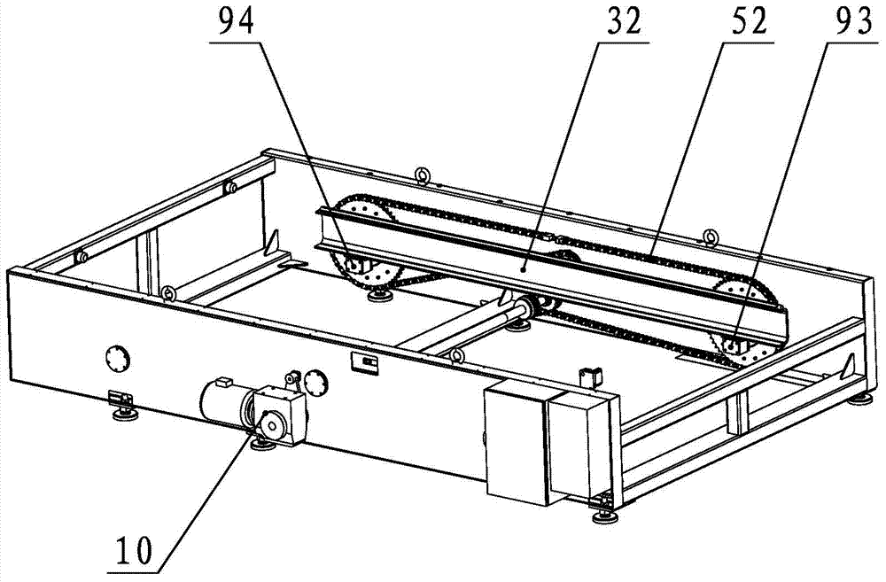
[0030] refer to Figures 1 to 5 , the chain-driven lifting exchange workbench provided by the present invention includes a base 11, a left sprocket lifting system and a right sprocket lifting system respectively installed on the symmetrical inner side of the base 11, and is used to connect the left sprocket lifting system and the right sprocket lifting system. The synchronous shaft 12 of the system, and the cutting table synchronously driven by the left sprocket lifting system and the right sprocket lifting system, the synchronous shaft 12 is driven by the motor 10 and the reducer.

[0031] Wherein, the left sprocket lifting system includes the left driven large sprocket 61 / 62 installed on the two ends of the left side plate of the base 11 through bearings, and the left drivin...


PUM


Abstract

The invention discloses a chain transmission type lifting pallet changer. The chain transmission type lifting pallet changer comprises a base, a left chain wheel lifting system, a right chain wheel lifting system, a synchronizing shaft and a cutting workbench, wherein the left chain wheel lifting system and the right chain wheel lifting system are installed on the symmetrical inner sides of the base, the synchronizing shaft is used for connecting the left chain wheel lifting system and the right chain wheel lifting system, the cutting workbench is synchronously driven by the left chain wheel lifting system and the right chain wheel lifting system to ascend and descend, and the synchronizing shaft is driven by a motor and a speed reducer. The workbench is provided with four large chain wheels, the middle synchronizing shaft and four small chain wheels and is driven by chains to ascend and descend. Due to the fact that a chain transmission structure is ingeniously utilized, the desynchronizing problem in hydraulic ascending and descending is solved, the structure complexity and other problems caused by gear transmission and chain transmission are also solved, and cost is greatly saved.

Description

technical field [0001] The invention relates to a chain-driven lifting and exchanging workbench for a laser cutting machine. Background technique [0002] With the rapid development of the industry, customers' requirements for processing have been continuously improved, and higher requirements have been put forward for the reliability of machine tools. In the existing technology, the common lift and exchange tables for laser cutting machines have hydraulic lift and exchange work. There are some unstable factors in the above three kinds of lifting and exchange workbenches: [0003] ①The hydraulic lifting exchange table has the problem of multi-cylinder synchronization, that is, the hydraulic cylinders are not synchronized due to the different speeds in the liquid transportation, resulting in the deflection of the worktable during lifting and lowering, which is easy to damage the components of the workbench; in addition, there are hydraulic cylinders Leakage problem, that is,...

Claims


Application Information

Patent Timeline
Patent Type & Authority Applications(China)
IPC IPC(8): B23K26/70B23K26/38
CPCB23K26/083
Inventor 李正上孟凡昌黄兴义王吉云张士旭初兴业许厂陈坚肖俊清
Owner 苏州汇能激光科技有限公司
Learn More