Clamping device and method used for guaranteeing equality of extension lengths of two ends of through bolt

A core bolt and clamping device technology, applied in metal processing, metal processing equipment, manufacturing tools, etc., can solve the problems of different lengths at both ends of the core bolt, and it is difficult to grasp the extension length, etc. Reduce operation steps and improve the effect of construction progress

Active Publication Date: 2015-06-24
STATE GRID CORP OF CHINA +1
View PDF6 Cites 3 Cited by
  • Summary
  • Abstract
  • Description
  • Claims
  • Application Information

AI Technical Summary

Problems solved by technology

[0005] In view of the prior art, the core-through bolts are manually installed, and it is not easy for workers to grasp the protruding lengths of both ends of the core-through bolts during construction, resulting in the problem that the protruding lengths of the two ends of the core-through bolts are different. The purpose of the present invention is to Provide a clamping device and method for ensuring that the protruding lengths of both ends of the core-through bolt are equal, and accurately control the protruding length of the two ends of the core-through bolt during the installation process to achieve a uniform effect

Method used


Image

  • Clamping device and method used for guaranteeing equality of extension lengths of two ends of through bolt
  • Clamping device and method used for guaranteeing equality of extension lengths of two ends of through bolt
  • Clamping device and method used for guaranteeing equality of extension lengths of two ends of through bolt

Examples


Embodiment Construction

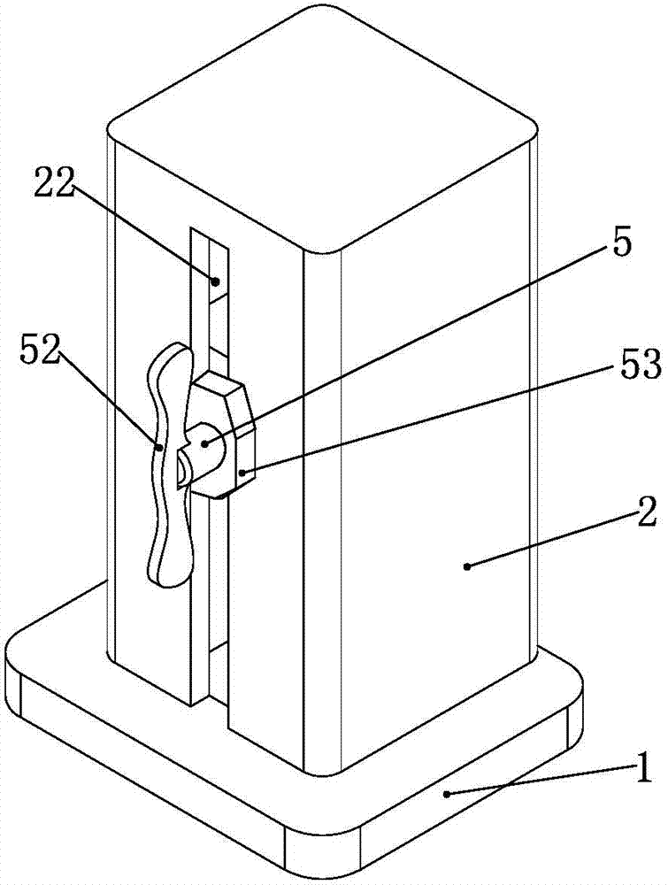
[0034] Such as Figure 1 to Figure 5 As shown, the present invention provides a clamping device for ensuring that both ends of a core-through bolt have equal extension lengths. It includes a magnetic base 1 on which axially arranged through holes 12 are provided.

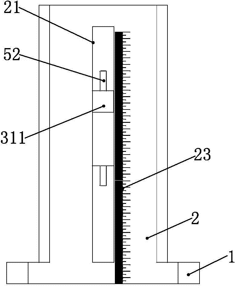
[0035] A housing 2 is vertically arranged on the base 1, and a first cavity 24 communicating with the through hole 12 is provided inside the housing 2, and first grooves communicating with the first cavity 24 are symmetrically provided on two opposite sides of the housing 2 Holes 21 and the second slot 22, the outer surface of the housing 2 on one side of the first slot 21 is provided with a scale 23, in a specific embodiment, as figure 2 As shown, the zero mark line of the scale 23 is flush with the bottom surface of the base 1. In specific use, when the base 1 is in contact with the lower flange, it is ensured that the zero mark line of the scale 23 starts from the end face of the lower flange.

[0036] Such as ...


PUM


Abstract

The invention provides a clamping device and method used for guaranteeing equality of the extension lengths of the two ends of a through bolt. The clamping device and method mainly solve the problem that the extension lengths of the two ends of a through bolt are not equal when the through bolt is mounted manually. The clamping device comprises a magnetic base and a shell, wherein the magnetic base can be attracted to a flange, and the shell is perpendicularly arranged on the base; the shell is internally provided with a first cavity communicated with a through hole in the base, and the two opposite side faces of the shell are symmetrically provided with a first slot hole and a second slot hole; a ruler is arranged at one side of the first slot hole in the shell, and the zero graduation line of the ruler is flush with the bottom face of the base; the first cavity is internally provided with a first V-shaped block and a second V-shaped block which are provided with opposite openings; a threaded rod capable of rotating along the second slot hole is arranged at one side of the second slot hole; the part, on the outer side of the second slot hole, of the threaded hole is provided with a movable nut; the threaded rod is rotated, the first V-shaped block moves towards the second V-shaped block and clamps the through bolt, and the position of the threaded rod is fixed through the movable nut. The clamping device is simple in structure, convenient to use and capable of effectively guaranteeing the equality of the extension lengths of the two ends of the through bolt.

Description

technical field [0001] The invention relates to the technical field of engineering equipment installation, in particular to a clamping device and method for ensuring that the protruding lengths of both ends of a core-through bolt are equal. Background technique [0002] In the process of engineering equipment installation, pipeline installation is very common. As a common pipeline connection method, flange connection means that flanges are cast at both ends of the pipeline, and there is a seal on the end face of the flange. The groove is equipped with a sealing ring, and the pipes are tightly connected together with bolts or core bolts after butt joint. The flange connection method is widely used in pipeline connections in many fields such as electric power, petroleum, and chemical industry. Usually, there will be liquids in the connected pipelines. These liquids are oil or other dangerous chemical raw materials, such as cooling oil for large transformers. The circuit conta...

Claims


Application Information

Patent Timeline
Patent Type & Authority Applications(China)
IPC IPC(8): B23P19/10
CPCB23P19/10
Inventor 王伟张彦高华伟单波唐爽韩义成陈新刚李洋刘宁朱毅屠庆波王艳梅靳书栋郝铁军韩延峰李彦刘宏志孔超闫勇钟治艳
Owner STATE GRID CORP OF CHINA
Why Eureka
Try Eureka