
Linear Motor Assembly And Machine Tool With Linear Motor Assembly

A linear motor and coil device technology, applied in the field of machine tools, can solve the problems of large machine tool structure space requirements, high equipment technology costs, etc., and achieve the effects of cost saving and high measurement accuracy

Inactive Publication Date: 2015-06-24
ROBERT BOSCH GMBH
View PDF10 Cites 6 Cited by
  • Summary
  • Abstract
  • Description
  • Claims
  • Application Information

AI Technical Summary

Problems solved by technology

[0004] The disadvantage of this technical solution is the relatively high technical equipment costs and the large structural space requirements of the machine tool

Method used


Image

  • Linear Motor Assembly And Machine Tool With Linear Motor Assembly
  • Linear Motor Assembly And Machine Tool With Linear Motor Assembly
  • Linear Motor Assembly And Machine Tool With Linear Motor Assembly

Examples


Embodiment Construction

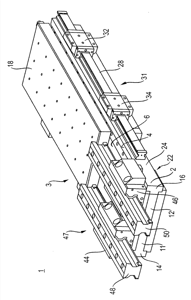
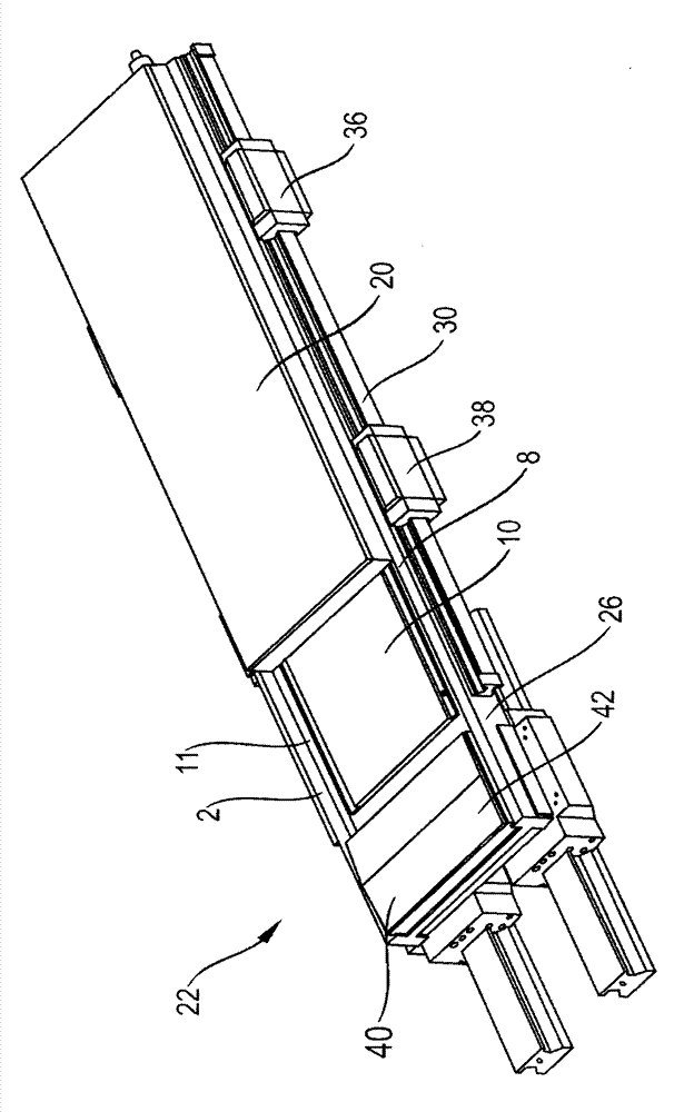
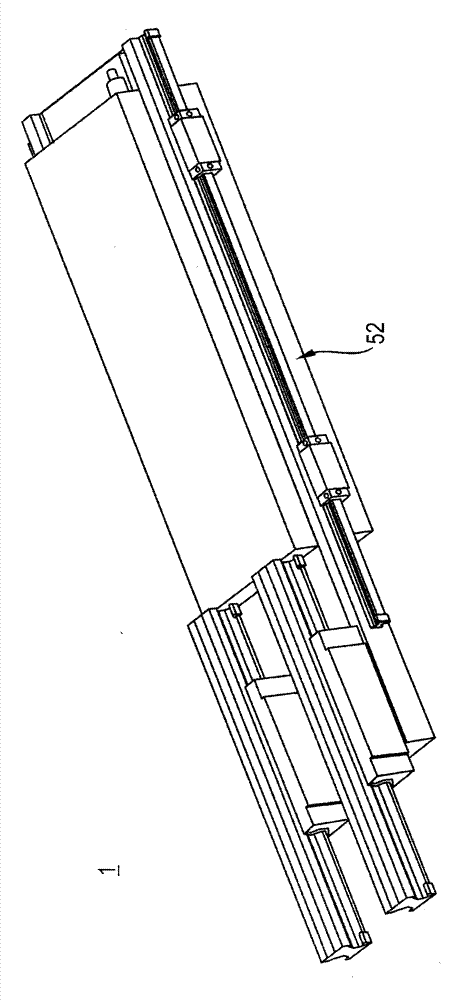
[0068] according to figure 1 A linear motor arrangement 1 for a nibbling machine is shown, extending approximately in the horizontal direction, with a linear motor 3 . The linear motor arrangement has a slide carriage 2 on the upper slide carriage side of which a secondary unit in the form of a magnetic arrangement is arranged. On the side 8 of the lower sliding bracket of the sliding bracket according to figure 2 A further secondary unit in the form of a magnetic device 10 is provided. according to figure 1 , the sliding bracket 2 has, viewed in cross section, a support plate 11 with an H-shaped profile, which has a connecting web 12 and two side webs 14 and 16 . The magnetic devices 6 and 10 are each located on a connection web 12 and thus arranged between webs 14 and 16 . The magnetic devices 6 and 10 each have an approximately plate-shaped housing, which is preferably screwed to the slide carrier 2 . A primary unit in the form of a coil arrangement 18 is arranged opp...


PUM


Abstract

The present invention discloses a linear motor assembly used for a stepping machine tool. The linear motor assembly is provided with a linear motor with two secondary units which are arranged on a supporting plate of a sliding support, and each secondary unit is equipped with a primary unit. The supporting plate is sandwiched between the primary units, and the sliding support guides and supports movably along a longitudinal direction via at least one linear guide device. The sliding support can apply an operating force on a cutter at the end side, wherein the operating force is basically vertical with a longitudinal axis to play part.

Description

technical field [0001] The invention relates to a linear motor arrangement according to the preamble of claim 1 and to a machine tool (nibbling machine tool) having such a linear motor arrangement. Background technique [0002] A machine tool with a spindle drive is known from EP 1 299 200 B1. A wedge can be pushed in the horizontal direction by means of the spindle drive. The tool of the machine tool can be manipulated in the vertical direction by means of the wedge. [0003] A similar machine tool is known from EP 2 527 058 A1, with which a linear motor can be used instead of the spindle drive. [0004] Disadvantages of this technical solution are the relatively high technical equipment costs and the large structural space requirements of the machine tool. Contents of the invention [0005] In contrast, the object of the present invention is to create a linear motor arrangement which has a compact design and at the same time provides high forces and low moving masses....

Claims


Application Information

Patent Timeline
Patent Type & Authority Applications(China)
IPC IPC(8): B23Q5/34B23Q1/58H02K41/02
CPCB30B1/10B30B1/40H02K7/02H02K7/08H02K16/00H02K41/02B30B1/008B30B1/261B30B1/266
Inventor R·凯勒
Owner ROBERT BOSCH GMBH
Learn More