Cutting machine with fan

A cutting machine and fan technology, which is applied in the direction of grinding machines, metal processing equipment, grinding/polishing equipment, etc., can solve the problem that the cutting machine does not have the function of relieving heat and cooling, and achieves the effect of convenient disassembly

Inactive Publication Date: 2015-06-24
XIAN YUHUA IND DEV
View PDF0 Cites 0 Cited by
  • Summary
  • Abstract
  • Description
  • Claims
  • Application Information

AI Technical Summary

Problems solved by technology

[0003] The purpose of the invention is to overcome the problem that the current cutting machine does not have the function of relieving heat and cooling

Method used


Image

  • Cutting machine with fan

Examples


Embodiment 1

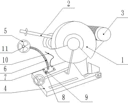
[0011] Embodiment 1: as figure 1 A cutting machine with a fan, including a grinding wheel 1, a motor 2, a handle 3, and a base plate 4, is characterized in that an electric fan 5 is arranged on the cutting machine, and the electric fan 5 is connected with a base 7 by a connecting rod 6. The base 7 is fixed on the bottom plate 4 of the cutting machine with screws, the electric fan 5 is connected with the fan switch 8, the fan switch 8 is connected with the power supply 10, the power supply 10 is an independent power supply, protruding from the rear of the base 7, and connected with the external power supply .

[0012] The cutting machine with electric fan provided in this embodiment can install the electric fan on the cutting machine when the temperature is high in summer, and turn on the electric fan to achieve the purpose of relieving heat and cooling down, while in autumn and winter, the temperature is low. When not in use, it can be removed directly, which is convenient an...

Embodiment 2

[0013] Embodiment 2: This embodiment is basically the same as Embodiment 1, the difference is that: the connecting rod 6 is a universal tube adjustable in one direction, and the staff can arbitrarily adjust the angle and direction of the electric fan during work. Position, to achieve the goal of not affecting the work, but also maximizing the role.

[0014] There is also an LED light group 11 in the center of the electric fan 5, which is connected to the LED light switch 9 in the base 7 through the connecting rod 6, and the LED light switch 9 is directly connected to the power supply 10. At night or when the lighting conditions are not good, the electric fan It can also be used as a lighting lamp.


PUM


Abstract

A cutting machine with a fan comprises a grinding wheel, a motor, a handle and a bottom plate. The cutting machine is characterized in that the electric fan is arranged on the cutting machine and is connected with a base through a connecting rod, the base is fixed on the bottom plate of the cutting machine through screws, the electric fan is connected with a fan switch, the fan switch is connected with a power source, and the power source, namely an independent power source, extends from the rear portion of the base to be connected with an external power source. The cutting machine has the advantages that the problem that existing cutting machines do not have cooling functions is solved; when the air temperature is high in summer, the electric fan is mounted on the cutting machine and is turned on to achieve cooling effect; when the air temperature is low in autumn and winter, the electric fan is not needed and is demounted directly, and convenience and rapidness are achieved; the cutting machine is in threaded connection with the electric fan, convenience in demounting and safety and firmness in use are achieved, and accordingly, the connection mode is a best choice for machine tool mounting.

Description

technical field [0001] The invention belongs to the field of electromechanical technology, and in particular relates to a cutting machine with a fan. Background technique [0002] Cutting machine is a kind of commonly used electromechanical equipment. It is used for industrial cutting. This operation is tedious and time-consuming, and the surrounding environment is often poor. The electric fan can provide a cool environment for people at work, which will greatly facilitate the daily work of the operator. Contents of the invention [0003] The purpose of the invention is to overcome the problem that the current cutting machine does not have the function of relieving heat and cooling down. [0004] For this reason, the invention provides a cutting machine with a fan, including a grinding wheel, a motor, a handle, and a bottom plate. An electric fan is also arranged on the cutting machine, and the electric fan is connected with a base by a connecting rod, and the base is fix...

Claims


Application Information

Patent Timeline
IPC IPC(8): B24B27/06
CPCB24B27/08B24B55/00
Inventor 毕义强
Owner XIAN YUHUA IND DEV
Why Eureka
Try Eureka