Eureka AIR delivers breakthrough ideas for toughest innovation challenges, trusted by R&D personnel around the world.

Chemical storage tank

A storage tank and chemical technology, applied in the direction of tank cars, transport passenger cars, railway car body parts, etc., can solve the problems of difficulty in taking out, increased viscosity of chemicals, slow flow of storage tanks, etc., and achieves the effect of improving heat dissipation efficiency.

Inactive Publication Date: 2015-06-24
TIANJIN HUAJINPU CHEM
View PDF0 Cites 3 Cited by
  • Summary
  • Abstract
  • Description
  • Claims
  • Application Information

AI Technical Summary

Problems solved by technology

[0002] In the chemical field, it is often necessary to store chemical raw materials or finished chemical products in storage tanks. However, due to the decrease in temperature in winter, the viscosity of some chemicals increases, and the flow in the storage tank is slow, so it is very difficult to take them out.

Method used


Image

  • Chemical storage tank
  • Chemical storage tank

Examples


Embodiment Construction

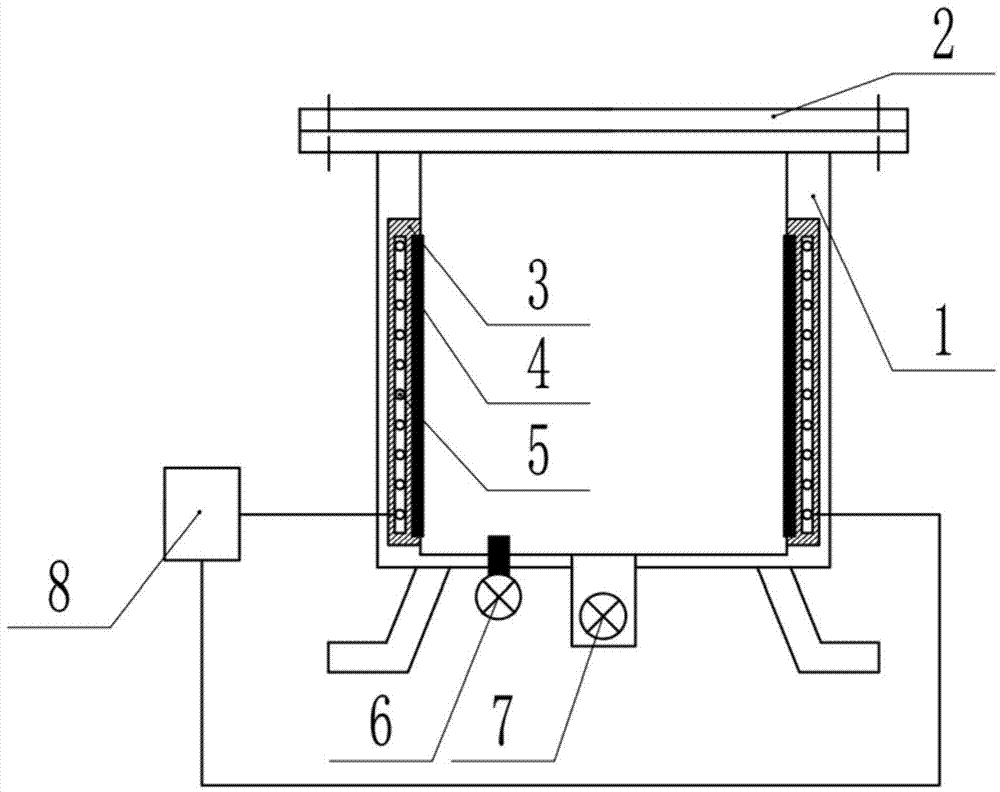
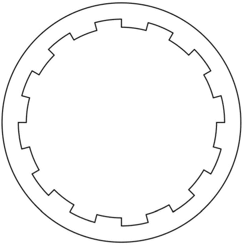
[0016] A chemical storage tank, comprising a tank body 1, the upper part of the tank body 1 is provided with a cover 2 that is movably connected thereto, the side wall of the tank body 1 is provided with an installation card slot, and a heat insulation device is installed in the installation card slot The felt block 3, the interior of the heat insulation felt block 3 is a hollow structure, and a heating wire 5 is arranged inside, and one side of the tank body of the heat insulation felt block 3 is a groove, and a phase change insulation layer 4 is arranged in the groove, and the phase change The inner side of the insulation layer 4 is provided with a plurality of bosses along the circumferential direction; the bottom of the tank body 1 is provided with a discharge port 7 fixed thereto, and a thermometer 6 is also provided.

[0017] In this embodiment: the heating wire 5 uses an AC power supply 8 as a power supply; the heat insulation felt block 3 is made of an airgel blanket; t...


PUM


Abstract

The invention provides a chemical storage tank. The chemical storage tank comprises a tank body, a seal cover movably connected with the tank body is arranged on the upper portion of the tank body, the side wall of the tank body is provided with a mounting clamping groove, a thermal insulation felt which is internally in a hollow structure is mounted in the mounting clamping groove, and heating wires are arranged in the heat insulation felt. One side, in the tank body, of the heat insulation felt is provided with a groove which is internally provided with a phase-variable heat insulation layer, and the inner side of the phase-variable heat insulation layer is peripherally provided with a plurality of bosses. The bottom of the tank body is provided with a discharging port fixed to the bottom of the tank body, and a thermometer is further arranged at the bottom of the tank body. Due to the facts that the heat insulation felt with the heating wires inside is mounted on the chemical storage tank, and one side, in the tank body, of the heat insulation felt is provided with the phase-variable heat insulation layer, heat is prevented from being released outside the tank body when the heating wires transfer heat to the phase-variable heat insulation layer; owing to the multi-boss structure of the inner side of the phase-variable heat insulation layer, heat radiation efficiency is improved, and quickness in transferring of heat to chemicals in the tank body is realized.

Description

technical field [0001] The invention relates to the field of chemical industry, in particular to a chemical storage tank. Background technique [0002] In the chemical field, it is often necessary to store chemical raw materials or finished products in storage tanks. However, due to the decrease in temperature in winter, the viscosity of some chemicals increases, and the flow in the storage tanks is slow, making it very difficult to take them out. Contents of the invention [0003] In order to solve the above problems, the present invention provides a chemical storage tank [0004] The specific technical solutions are: [0005] A chemical storage tank, comprising a tank body, the upper part of the tank body is provided with a cover that is movably connected with it, the side wall of the tank body is provided with an installation card slot, and a heat insulation felt block is installed in the installation card slot. The interior of the thermal felt block is a hollow struc...

Claims


Application Information

Patent Timeline
IPC IPC(8): B65D88/74B65D90/04B65D90/00
CPCB65D88/744B65D90/04B65D90/48
Inventor 冯玉生
Owner TIANJIN HUAJINPU CHEM
Why Eureka
Eureka Blog
Learn More