Soap printing device for improving imprinting quality

A soap printing and quality technology, applied in the direction of embossing/polishing soap, cutting soap, etc., can solve the problems of large deformation, poor consistency and unsightly appearance of handmade soap, so as to improve the quality of printing, production efficiency and easy operation. Effect

Inactive Publication Date: 2015-06-24
申清章
View PDF0 Cites 0 Cited by
  • Summary
  • Abstract
  • Description
  • Claims
  • Application Information

AI Technical Summary

Problems solved by technology

However, due to the different proficiency of the embossers, the imprints of the characters and pictures are of different depths, poor consistency, an

Method used


Image

  • Soap printing device for improving imprinting quality
  • Soap printing device for improving imprinting quality
  • Soap printing device for improving imprinting quality

Examples


Embodiment 1)

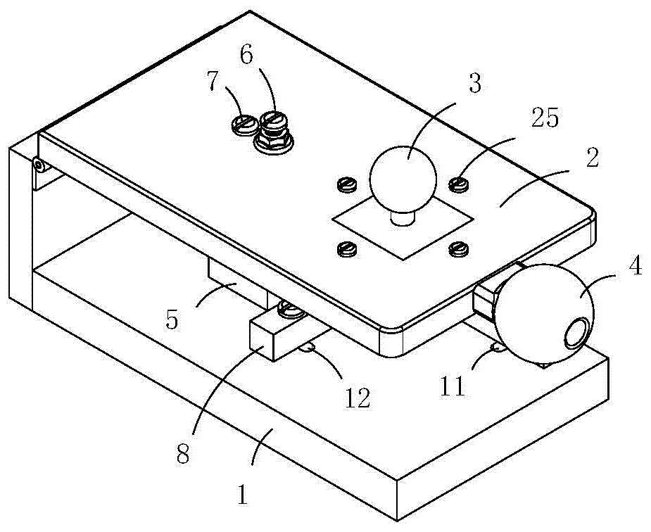
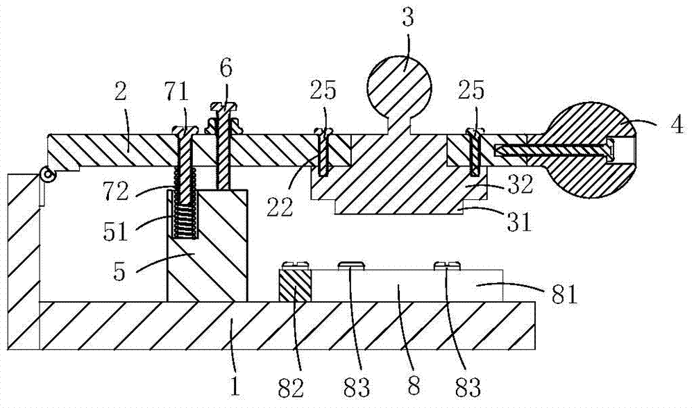
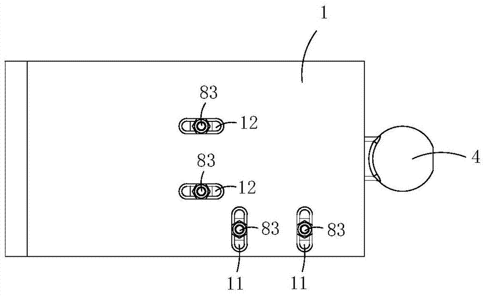
[0015] Present embodiment is a kind of soap printing device, see Figure 1 to Figure 6 As shown, it includes the base 1, the rotating pressing plate 2 set on the base, the soap stamp 3 fixed on the pressing plate, the handle 4 driving the pressing plate to rotate, the limiting boss 5 set on the base, and the adjusting bolt set on the pressing plate 6. The reset mechanism 7 and the position adjustment mechanism 8, the bottom end of the adjustment bolt protrudes downward from the pressure plate, and when the pressure plate rotates to the lowest position, it abuts against the limit boss.

[0016] The reset mechanism includes a reset limit post 71 arranged on the pressing plate and a reset spring 72 sleeved on the reset limit post. Stretch out from the part of the cylinder of the pressure plate; the limit boss is provided with a slide hole 51, and when the reset limit post rotates with the pressure plate, its bottom end can be inserted in the slide hole.

[0017] The position adj...

Embodiment 2)

[0022] This embodiment is basically the same as Embodiment 1, the difference is: see Figure 7 and Figure 8 As shown, it also includes a cutter 9; the pressing plate is provided with a slitting limit hole 23 and a crosscutting limit hole 24, and the base is provided with a slitting limit groove 13 adapted to the position of the slitting limit hole, and Transverse limiting groove 14 adapted to the position of the transverse limiting hole; the longitudinal limiting hole and the transverse limiting hole intersect to form an L shape, and the longitudinal limiting groove and the transverse limiting groove also meet to form an L shape ; The shape of the cutting knife is an L shape adapted to the vertical cutting limit hole and the transverse cutting limit hole.


PUM


Abstract

The invention discloses a soap printing device for improving imprinting quality. The soap printing device comprises a base, a pressure plate, a soap print, a handle, a limiting lug boss, an adjusting bolt, a resetting mechanism and a positioning mechanism, wherein the resetting mechanism comprises a resetting limiting column and a resetting spring; the pressure plate extends down out of the bottom end of the resetting limiting column; the resetting spring sleeves on a partial column body, which extends down out of the pressure plate downwards, of the resetting limiting column; a slide hole is formed in the limiting lug boss; the bottom end of the resetting limiting column can be inserted into the slide hole when the resetting limiting column rotates along with the pressure plate; the positioning mechanism comprises longitudinal adjusting baffle tables, transverse adjusting baffle plates and adjusting bolt assemblies; a longitudinal mounting hole group and a transverse assembly mounting hole group are formed in the base and are both waist holes; the longitudinal adjusting baffle tables penetrate through the adjusting bolt assemblies of the longitudinal assembly mounting holes and are fixedly arranged on the base; and the transverse adjusting baffle plates penetrate through the adjusting bolt assemblies of the transverse assembly mounting holes and are fixedly arranged on the base. According to the soap printing device, the imprinting quality and the production efficiency are effectively improved.

Description

technical field [0001] The present invention is a divisional application of an invention patent application with the filing date of August 27, 2013, the patent name "soap printing device", and the application number "201310378435.5". Background technique [0002] At present, with the improvement of people's living standards, handmade soap is more and more popular among women. After the handmade soap is solidified, most merchants like to emboss their own LOGO or other promotional characters on the soap body with soap stamps. The traditional embossing method is to hold a soap stamp and directly press it on the outer wall of the soap to obtain a word map. However, due to the different proficiency of the embossers, the imprints of the characters and pictures are of different depths, poor consistency, and unsightly. What's more, due to the excessive force during embossing, the handmade soap is deformed too much, and even crushed. Crack and become waste. Contents of the invent...

Claims


Application Information

Patent Timeline
IPC IPC(8): C11D13/28C11D13/22
Inventor 不公告发明人
Owner 申清章
Why Eureka
Try Eureka