Synthesis technology of prefabricated reinforcement cage

A technology of steel cages and steel bars, which is applied in the direction of manufacturing tools, ceramic molding machines, structural elements, etc., can solve problems such as labor-consuming and time-consuming, and achieve high recycling rates, improve production efficiency, and save time.

Active Publication Date: 2015-06-24
RENQIU YONGJI CONSTR & INSTALLATION ENG
View PDF6 Cites 3 Cited by
  • Summary
  • Abstract
  • Description
  • Claims
  • Application Information

AI Technical Summary

Problems solved by technology

[0004] The purpose of this invention is to provide a synthesis technology of prefabricated steel cages, which is mainly used for the synthesis of prefabricated sandwich reinforced concrete slabs in our company, replacing the labor-intensive and time-consuming problem of the original building construction, canceling the manual binding of steel cages, and improving production efficiency

Method used


Image

  • Synthesis technology of prefabricated reinforcement cage
  • Synthesis technology of prefabricated reinforcement cage
  • Synthesis technology of prefabricated reinforcement cage

Examples


Embodiment 1

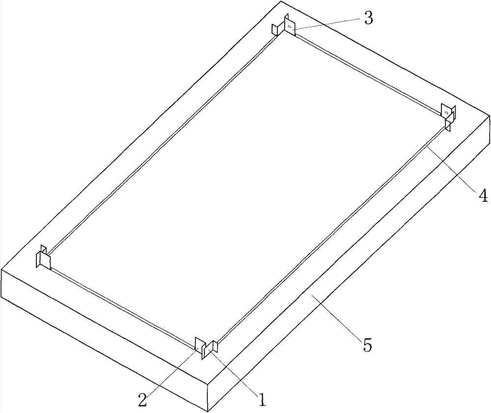
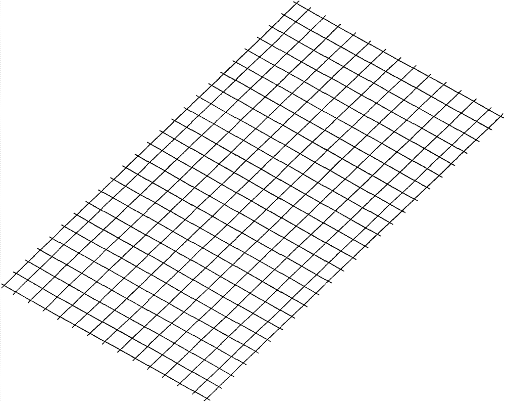
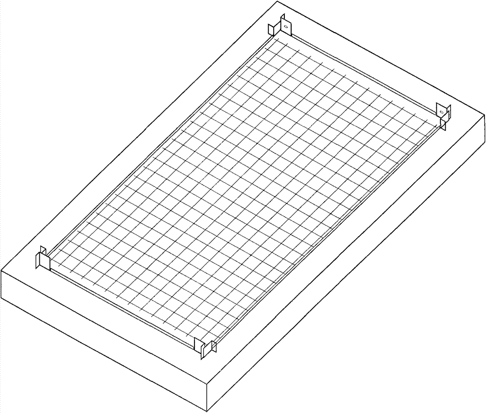
[0030] Use the steel bar straightening and cutting machine to straighten the coiled circular steel bars and cut them into the length required by the design to obtain steel bars of different sizes. The steel bars are welded by a steel bar spot welder to form a steel bar upper sheet (see figure 2 ) and mesh under the reinforcement (see figure 2 ). First synthesize the mold in the steel cage (see figure 1 ) and arrange the mesh under the reinforcement (see figure 2 ),Such as image 3 shown. On one side of the steel sheet with a width of 260mm, weld the bent protruding stirrups and ring-shaped stirrups to make the protruding stirrup frame (see Figure 7 ), where the stirrup spacing is 200mm. Weld the prefabricated raised stirrup frame on the four sides of the mesh under the steel bar (see Figure 7 ), and finally weld the upper mesh of the steel bar to the frame of the prefabricated raised stirrup (see Figure 10 ), the formed prefabricated reinforcement cage 1 can be o...

Embodiment 2

[0032] Use the steel bar straightening and cutting machine to straighten the coiled circular steel bars and cut them into the length required by the design to obtain steel bars of different sizes. The steel bars are welded by a steel bar spot welder to form a steel bar upper sheet (see figure 2 ) and mesh under the reinforcement (see figure 2 ). First synthesize the mold in the steel cage (see figure 1 ) and arrange the mesh under the reinforcement (see figure 2 ),Such as image 3 shown. Weld the bent concave stirrups and ring-shaped stirrups on one side of the steel sheet with a width of 260mm to make the frame of the concave stirrups (see Figure 8 ), where the stirrup spacing is 200mm. Weld the prefabricated concave stirrup frame on the four sides of the mesh under the steel bar (see Figure 8 ), and finally weld the upper mesh of the steel bar to the frame of the prefabricated concave stirrup (see Figure 11 ), the formed prefabricated reinforcement cage 2 can b...

Embodiment 3

[0034] Use the steel bar straightening and cutting machine to straighten the coiled circular steel bars and cut them into the length required by the design to obtain steel bars of different sizes. The steel bars are welded by a steel bar spot welder to form a steel bar upper sheet (see figure 2 ) and mesh under the reinforcement (see figure 2 ). First synthesize the mold in the steel cage (see figure 1 ) and arrange the mesh under the reinforcement (see figure 2 ),Such as image 3 shown. Weld the bent ring stirrup on one side of the steel sheet with a width of 260mm to make the frame of the ring stirrup (see Figure 9 ), where the stirrup spacing is 200mm. Weld the prefabricated ring stirrup frame on the four sides of the mesh under the steel bar (see Figure 9 ), and finally weld the reinforcement mesh to the frame of the prefabricated ring stirrup (see Figure 12 ), the formed prefabricated reinforcement cage 3 can be obtained (see Figure 15 ), sent to synthesiz...


PUM

PropertyMeasurementUnit
diameteraaaaaaaaaa

Abstract

The invention relates to a synthesis technology of a prefabricated reinforcement cage. Reinforcement bars are welded by virtue of a reinforcement bar spot welding machine to form a reinforcement bar upper mesh and a reinforcement bar lower mesh, the reinforcement bar lower mesh is well arranged in a reinforcement cage synthesis mold, a prefabricated hooped frame is welded on the periphery of the reinforcement bar lower mesh, and finally the reinforcement bar upper mesh is welded onto the prefabricated hooped frame to obtain the prefabricated reinforcement cage. According to different design requirements, different reinforcement cages can be produced, and the produced reinforcement cage can be sent to be synthesized into a prefabricated sandwiched reinforcement bar concrete plate. By adopting the synthesis technology, the time of the production line of the prefabricated sandwiched reinforcement bar concrete plate can be saved, the production efficiency is improved, and a part is enabled to realize the standardized production. The reinforcement bar electric welding machine substitutes the manual binding way; the reinforcement cage synthesis mold can be applied to the assembly line, and the cycling utilization rate is high; the problems of the original building construction method that labor and time are wasted can be solved.

Description

Technical field: [0001] The invention belongs to the field of building construction, and relates to a synthesis technology of a prefabricated steel reinforcement cage for construction, which is suitable for our company's prefabricated sandwich reinforced concrete slab assembled housing. Background technique: [0002] During the construction of traditional buildings, steel cages are arranged inside the columns and beams in the buildings, and then grouted to them, so as to play a supporting role inside the buildings. Reinforcement cages are generally composed of several main steel bars, stirrups and tie bars. Several main steel bars are longitudinally penetrating steel bars; To achieve the effect of confinement; the number of bars is the reinforcement of the main reinforcement of the lateral confinement part, which respectively have X direction and Y direction, and can have the effect of strengthening the stirrup. [0003] The prefabricated sandwich reinforced concrete slab i...

Claims


Application Information

Patent Timeline
Patent Type & Authority Applications(China)
IPC IPC(8): E04C5/06B28B23/02
Inventor 朱连吉熊春燕
Owner RENQIU YONGJI CONSTR & INSTALLATION ENG
Why Eureka
Try Eureka