Radial impeller and fan assembly

A radial flow and impeller technology, applied in radial flow pumps, pump components, mechanical equipment, etc., to increase efficiency and promote noise reduction

Active Publication Date: 2015-06-24
EBM PAPST MULFINGEN GMBH & CO KG
View PDF6 Cites 5 Cited by
  • Summary
  • Abstract
  • Description
  • Claims
  • Application Information

AI Technical Summary

Problems solved by technology

Disadvantageously, the vortex at the top disc is enhanced by known profiled blades
Thus, this means only a very slight increase in efficiency

Method used


Image

  • Radial impeller and fan assembly
  • Radial impeller and fan assembly
  • Radial impeller and fan assembly

Examples


Embodiment Construction

[0107] In the different figures of the drawings, identical parts or functionally identical parts are indicated by the same reference numerals and symbols. However, if specific features described and / or which can be deduced from the drawing or configuration of a radial impeller or fan unit according to the invention are mentioned only in relation to an embodiment, then the embodiment is according to the invention and not dependent on this embodiment. , these features are notable as individual features or also in combination with other features of the embodiment and may be claimed to belong to the present invention.

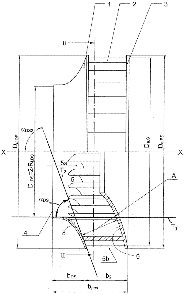
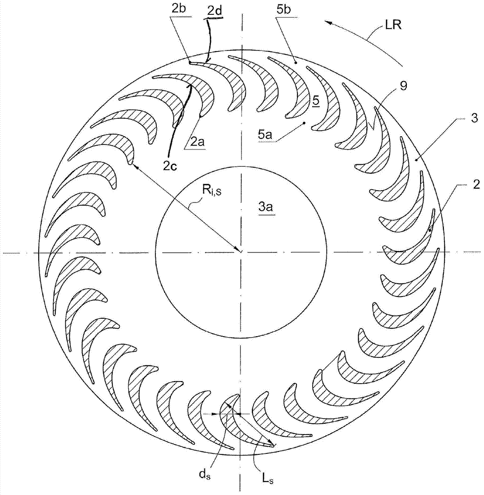
[0108] as first available from figure 1 and figure 2 As seen in , a radial impeller 10 according to the invention has a top disc 1 , a plurality of forward-curved profiled blades 2 and a bottom disc 3 . The top disc 1 forms a suction hole and thus has a circular suction opening 4 for the axial air inlet, the suction opening 4 having an inner diameter D i,DS . ...


PUM


Abstract

An impeller has an inlet and outlet. A bottom disc has an external diameter. A top disc concentric to the bottom disc at an axial distance therefrom has a suction opening for the inlet. A plurality of forward-curved blades are arranged between the bottom disc and the top disc. A flow channel has an inner inlet side and an outer outlet side formed between adjacent blades. The channel is curved convexly viewed in the running direction of the impeller. The external diameter of the bottom disc is at least 20% greater than the internal diameter of the suction opening. The top disc forms a guiding surface and an angle is formed between a tangent on the guiding surface at the inlet to the suction opening and a tangent on the guiding surface at the outlet from the flow channel on the air outlet side is at least 30°.

Description

technical field [0001] The present invention relates to a radial impeller for a blower, having an axial air inlet and an air outlet on the periphery of the impeller, preferably used in a helical housing, said radial impeller comprising : a bottom disc and a top disc, the bottom disc has an outer diameter, the top disc is arranged concentrically with the bottom disc at an axial distance from the bottom disc, and the top The disc has a circular suction opening for the axial air inlet, the intake opening has an inner diameter, and the radial impeller further includes multiple impellers disposed between the bottom disc and the top disc. forward-curved profiled blades, a flow channel formed in each case between two adjacent blades with a radially inner air inlet side and a radially outer air outlet side, when viewed in the direction of operation of a radial impeller , the flow channel is convexly curved. The runner curvature means that the suction side surface of the vane is at l...

Claims


Application Information

Patent Timeline
Patent Type & Authority Applications(China)
IPC IPC(8): F04D29/28
CPCF04D29/281F04D29/666F04D29/282F04D29/30F04D29/4226F04D29/667F04D29/4233F04D29/681F04D17/08F04D29/22F04D29/441
Inventor D·格伯特K·博尔E·赖克特
Owner EBM PAPST MULFINGEN GMBH & CO KG
Why Eureka
Try Eureka