High-strength oil seal

A sealing oil and high-strength technology, which is applied in the direction of engine sealing, engine components, mechanical equipment, etc., can solve the problems of easy wear of rubber sealing lips, large friction coefficient, and leakage of lubricating oil, and achieve good automatic compensation ability and extended The effect of service life and good sealing effect

Inactive Publication Date: 2015-06-24
TIANJIN QIXING PRECISION MACHINERY
View PDF0 Cites 4 Cited by
  • Summary
  • Abstract
  • Description
  • Claims
  • Application Information

AI Technical Summary

Problems solved by technology

In order to have a strong automatic compensation effect, the sealing lip, sealing lip and dust lip of the oil seal are installed with a relatively large specific pressure, and due to the large friction coefficient and high elastic modulus of the rubber itself, with the high-speed operation of the shaft Due to the change of high and low temperature working environment, the shaft is tightly hugged so that there is no lubricating oil film between the sealing lip and the shaft, which leads to dry friction between the sealing lip and the shaft, and "dry burning" occurs, and the rubber sealing lip is easy to wear
After improvement, the life of the oil seal is extended by lubricating the oil film on the friction contact surface. However, the size of the oil film is difficult to control. If the oil film is too large, the lubricating oil will leak, and if the oil film is too small, "dry burning" will occur.

Method used


Image

  • High-strength oil seal

Examples


Embodiment Construction

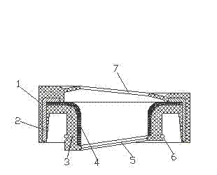
[0018] The accompanying drawing is a structural schematic diagram of the present invention. The high-strength sealing oil seal of the present invention includes a rubber body, a skeleton 2, a sealing lip 4 and a dust-proof lip 7. A sealing lip 5 is provided on the side of the sealing lip 4 where the oil comes from. The oil side refers to the lubricating oil side that needs to be sealed; the sealing lip 5 and the dustproof lip 7 are both internal helical structures, and the internal helical structure of the sealing lip 5 and the internal helical structure of the dustproof lip 7 The deployment direction is opposite, and the deployment direction of the internal helical structure of the dust-proof lip 7 is the same as the direction of rotation of the sealed shaft due to the oil incoming direction.

[0019] In this embodiment, the sealing lip 5 is integrally formed with the rubber body, the sealing lip 4 is made of polytetrafluoroethylene and its outer circle is bonded to the inner ...


PUM


Abstract

The invention discloses a high-strength oil seal. The high-strength oil seal comprises a rubber part, a framework, a seal lip and a dustproof lip. An oil incoming side of the seal lip is provided with a seal lip opening in an internal spiral structure, the dustproof lip is also in an internal spiral structure, the internal spiral structure of the seal lip opening and the internal spiral structure of the dustproof lip are opposite in expansion direction, and the expansion direction of the internal spiral structure of the dustproof lip is identical to the rotation direction of a sealed shaft from the oil incoming direction. Due to the spiral structures of the seal lip opening and the dustproof lip, effectiveness in pumping of oil and dust is achieved, the seal lip opening pumps oil into a lubricating oil tank under the action of mechanical force generated by shaft rotation, and the dustproof lip pumps dust out, so that excellent sealing effects can be achieved. The spiral structures enable high automatic compensation ability under the condition of low specific pressure, arrangement of sufficient oil films is not needed, and accordingly the problem of leakage of lubricating oil due to overlarge oil films is avoided, the condition of 'dry heating' is avoided as well, and service life of the oil seal is prolonged.

Description

technical field [0001] The invention relates to a sealing device, in particular to a shaft sealing oil sealing device. [0002] Background technique [0003] Shaft seal oil seals are indispensable components in various engines, gearboxes in the mechanical field, crankcases and other devices that require lubrication. In the prior art, the commonly used oil seal is composed of a metal skeleton, a rubber part with a sealing lip and a spring. The elasticity of the spring and the rubber itself makes the sealing lip and the shaft tightly contact to prevent the leakage of lubricating oil. , Play an automatic compensation role after the sealing lip is worn. In order to have a strong automatic compensation effect, the sealing lip, sealing lip and dust lip of the oil seal are installed with a relatively large specific pressure, and due to the large friction coefficient and high elastic modulus of the rubber itself, with the high-speed operation of the shaft Due to changes in the hi...

Claims


Application Information

Patent Timeline
Patent Type & Authority Applications(China)
IPC IPC(8): F16J15/32F16J15/3208F16J15/3232
CPCF16J15/3232F16J15/3208F16J15/3244F16J15/3268
Inventor 李洪建
Owner TIANJIN QIXING PRECISION MACHINERY
Why Eureka
Try Eureka