Anti-freezing rapid water taking valve

A water intake valve, fast technology, applied in the direction of lifting valve, valve details, valve device, etc., can solve problems such as easy water leakage and difficult connection

Active Publication Date: 2015-06-24
SHUANGYING ZHANGZHOU PRECISION METAL PROD CO LTD
View PDF10 Cites 11 Cited by
  • Summary
  • Abstract
  • Description
  • Claims
  • Application Information

AI Technical Summary

Problems solved by technology

In terms of taking water from the pipeline, the existing technology has connection difficulties, and there is a problem of water leakage when connecting

Method used


Image

  • Anti-freezing rapid water taking valve
  • Anti-freezing rapid water taking valve

Examples


Embodiment 1

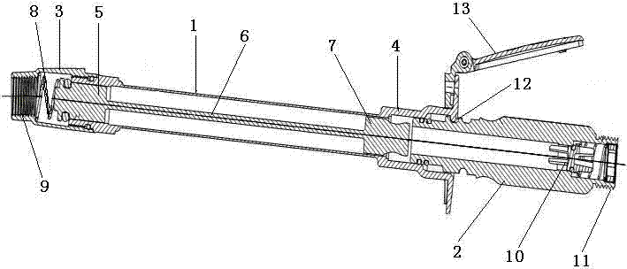
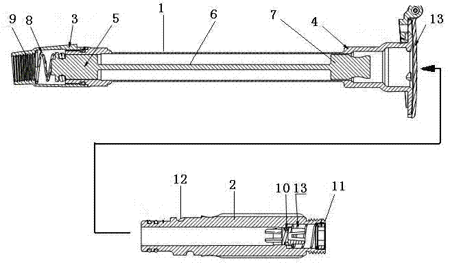
[0013] Embodiment 1: The length of the valve pipe 1 is set according to the thickness parameter requirements of the cold-proof and heat-insulating body. Connect the water supply connection end 9 of the upper valve body 3 to the running water pipe, and the lower valve body 4 presses on the inclined gasket 14 and inclines downward at 5° to fix it.

Embodiment 2

[0014] Embodiment 2: Connect the water diversion pipe to the water outlet connection end 11 of the valve handle body 2 as required, lift the windshield and dustproof cover 13, and snap the comma-shaped card slot 12 of the valve handle body 2 to the water intake valve of the lower valve body 4 The handle is connected to the card, the valve handle body 2 rotates along the spiral groove to produce a linear motion, and the upper end squeezes the lower piston 7 to move upward, and the lower piston pushes the upper piston 5 to move upward through the connecting rod 6, so that the lower piston 7 and the upper piston 5 move simultaneously. When the water flow channel is formed between the lower valve body 4 and the inner wall of the upper valve body 3, the return spring 8 is compressed to accumulate force for the return of the piston. Tap water flows through the inner cavity of the upper valve body 3, the valve pipe 1, the lower valve body 4, and the valve handle body 2, and is transpo...

Embodiment 3

[0015] Embodiment 3: When it is necessary to stop taking water, reverse the valve handle body 2 and take it out. At this time, because of the double protection of the double sealing ring, when the valve handle body 2 is moving outward, the return spring 8 is stretched to push the piston back to close the inner cavity of the upper valve body 5, and the sealing ring of the valve handle body 2 has not yet completely When leaving the position, the pressure in the valve pipe 1 has been reduced, preventing the spraying of water; there is a time difference between the upper piston 5 closing the inner cavity channel of the upper valve body 3 and pressing the sealing ring. During this time difference, there is a gap between the lower piston 7 and the inner cavity of the lower valve body 4, and the water remaining in the valve tube 1 is discharged due to inclination. When the sealing ring of the upper piston 5 is completely compressed, the remaining water is emptied, and the lower pisto...


PUM


Abstract

The invention provides an anti-freezing rapid water taking valve. The anti-freezing rapid water taking valve is composed of a water taking valve body and a water taking valve handle. The water taking valve body is composed of a valve pipe, an upper valve main body, a lower valve main body and a piston. The length of the valve pipe can be designed according to parameter requirements of a cold-proof heat preservation body. The upper valve main body is connected to the upper end of the valve pipe and provided with a water supply connecting end. When the water supply connecting end is installed, it is guaranteed that the central axis of the water taking valve body and the horizontal plane form an included angle of 5 degrees. The lower valve main body is connected to the lower end of the valve pipe and comprises a water taking valve handle connecting clamp and a windproof dustproof cover. The piston is composed of an upper piston body, a connecting rod, a lower piston rod body and a reset spring, wherein the upper piston body and the lower piston body are installed in inner cavities of the upper valve main body and the lower valve main body respectively, the connecting rod is in the valve pipe and connects the upper piston body and the lower piston body, and the reset spring is arranged between the water supply connecting end and the upper piston body. The water taking valve handle is rapidly connected with the water taking valve body through a comma-shaped clamping groove in the water taking valve handle, and then water supply is achieved.

Description

technical field [0001] The invention relates to an anti-freeze fast water intake valve, in particular to a water intake valve which passes through a cold-proof insulation body, automatically drains residual water as a transition, and can quickly connect pipelines, belonging to the technical field of hardware and plumbing. Background technique [0002] In the cold winter in northern my country, the water in the outdoor faucet often freezes due to the low temperature, causing the faucet to fail to open or even the pipeline to burst. People usually adopt the measures of covering heat preservation articles on the faucet to prevent freezing. Due to the special structure of the faucet, the heat preservation effect of adopting a simple covering method is not ideal. Moreover, after covering the heat preservation articles, it not only takes up space, but also affects the use of the faucet. This situation has always troubled people in the vast areas of the north, especially in some s...

Claims


Application Information

Patent Timeline
Patent Type & Authority Applications(China)
IPC IPC(8): F16K1/12F16K1/32
CPCF16K1/12F16K1/32F16K31/50F16K31/60
Inventor 理查德·威尔康肖怿
Owner SHUANGYING ZHANGZHOU PRECISION METAL PROD CO LTD
Why Eureka
Try Eureka